Problem
The frequency response of my system isn't flat. I want to fix it.
Plan
I want to add a notch filter to my tweeter and convert the 1st order crossover to a 2nd order. Then lower the crossover point of my mid woofer. This should allow me to crossover the mid and tweeter in the 2-3k range rather than 4k.
I'm aware that I'll need to measure the speaker myself to fine-tune crossover but I want to make sure I'm on the right track before I proceed.
Questions
1. Is it okay to remove the zobal network and replace it with an l-pad? I can use between a 7.5 to 10 ohm resistor in parallel with the mids.
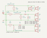
2. The 0.55mH inductors and 10uF caps form a 2nd order crossover at 2.15kHz? And I can lower the capacitors to raise the crossover frequency?
3. I can raise or lower the padding resistors to adjust the mid and tweeter level if necessary?
4. Are non inductive resistors necessary? I'm sure they're necessary in radio frequencies but I'm not sure they're necessary in audio crossovers. Does anyone know the inductance of Vishay RS resistors?
Old crossover
https://elektrotanya.com/allison-acoustics_one-and-two_schematic_before_6-80.pdf/download.html
New crossover
Additional info
Speaker frequency response and impedance measurement
https://www.gammaelectronics.xyz/audio_04-1976_allison.html
Allison tweeter measurement
https://www.diyaudio.com/community/threads/tweeters-in-allison-loudspeakers.294463/#post-4835097
http://www.classicspeakerpages.net/...on_one_series_brochure_15.html#previous-photo
The frequency response of my system isn't flat. I want to fix it.
Plan
I want to add a notch filter to my tweeter and convert the 1st order crossover to a 2nd order. Then lower the crossover point of my mid woofer. This should allow me to crossover the mid and tweeter in the 2-3k range rather than 4k.
I'm aware that I'll need to measure the speaker myself to fine-tune crossover but I want to make sure I'm on the right track before I proceed.
Questions
1. Is it okay to remove the zobal network and replace it with an l-pad? I can use between a 7.5 to 10 ohm resistor in parallel with the mids.
2. The 0.55mH inductors and 10uF caps form a 2nd order crossover at 2.15kHz? And I can lower the capacitors to raise the crossover frequency?
3. I can raise or lower the padding resistors to adjust the mid and tweeter level if necessary?
4. Are non inductive resistors necessary? I'm sure they're necessary in radio frequencies but I'm not sure they're necessary in audio crossovers. Does anyone know the inductance of Vishay RS resistors?
Old crossover
https://elektrotanya.com/allison-acoustics_one-and-two_schematic_before_6-80.pdf/download.html
New crossover
Additional info
Speaker frequency response and impedance measurement
https://www.gammaelectronics.xyz/audio_04-1976_allison.html
Allison tweeter measurement
https://www.diyaudio.com/community/threads/tweeters-in-allison-loudspeakers.294463/#post-4835097
http://www.classicspeakerpages.net/...on_one_series_brochure_15.html#previous-photo
Attachments
Last edited:
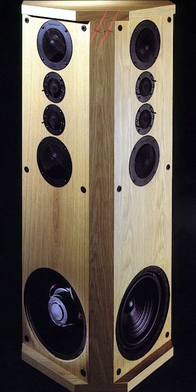
Here's a couple of images of this speaker. The photo may be the later IC20, but you get the idea. It is placed close to the wall.
The woofer close to the floor avoids a thing called floor bounce cancellation aka the Allison effect.

The woofer close to the floor avoids a thing called floor bounce cancellation aka the Allison effect.

Based on these charts. What crossover point is most optimal? 3400hz? 3750hz? or 4150hz?
Allison One Series Brochure (1978) pg10 | The Classic Speaker Pages
Allison One Series Brochure (1978) pg10 | The Classic Speaker Pages
I'm not sure that's enough information.
From your question it seems as though you want to put in a generic crossover. If you do you might get more than you expect.
Where to go from here depends on your tools and strengths. One way you might find enlightening is to shift the current crossover a little up and down, which you could do by changing the current values by small amounts, say 20%.
You could also experiment with some EQ, looking to trim trouble areas and set a general tone.
No, just recap. I can change the cap values from 3uF to 2.7 or 3.3uF to change the crossover point. Likewise change the 6.2uF to 5.6 or 6.8.
Changing the odd capacitor from say 3uf to 2.7uF should be inaudible. This is a 5% difference in crossover point. It's a square root relationship. The coils look like aircoils, which is fine. Resistors are resistors IMO, and don't age.
I might sim this one when I have time. But A DC resistance measurement on the drivers would be interesting and help me. If you disconnect the amplifier leads, you should get an accurate reading straight across the driver terminals except for the parallel woofers which will give a combined reading for the two. Did you use NP electrolytics here?
I don't much like tweeters on a single capacitor, so might look into that.
7.86 for the entire system.
3.71 for each midrange.
2.6 for each twitter.
Correct
No. I used film.
3.71 for each midrange.
2.6 for each twitter.
air coils
Correct
Did you use NP electrolytics here?
No. I used film.
I don't much like tweeters on a single capacitor, so might look into that.
What do you think about using a 3.3uF capacitor with a 0.20mH inductor in parallel with the tweeters?
I was thinking a second or third order on the dome tweeters might be good. Dome midranges for the record.
The woofers must be 16 ohm jobbies. Will sim it this wekend and see how it looks.
7.86 for the entire system.
3.71 for each midrange.
2.6 for each twitter.
The woofers must be 16 ohm jobbies. Will sim it this wekend and see how it looks.
I think increasing the crossover order and then lowering tweeter's crossover frequency a bit would make the speakers sound a little better.
Last edited:
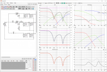
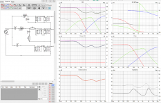
I've been experimenting in VituixCAD. I think that I can replace the 3uF tweeter cap with 3.3uF and 0.35mH inductor to create a 2nd order crossover. The graphs are look fairly similar to the original spec. Can someone explain the phase, power & di and directivity (hor) charts? I'm not sure if I am optimizing correctly.
Attachments
Is there any way to upgrade my crossover more? I recently rebuild my Allison Two crossover with new caps and resistors. I did change the values slightly to use modern caps.
*60uFD -> 56uFD
*35uFD -> 33uFD
*6.2uFD -> 5.6uFD
*3uFD (3.1uFD measured) -> 2.7uFD
It is easy to make almost exact values with paralleling two caps:
60 = 33+27 (or because you already have 56, then: 56+3.3 or 56+4.7)
35 = 33+2.2
6.2 = 5.6+0.56
3 = 2.7+0.27
Last edited:
I've been experimenting in VituixCAD. I think that I can replace the 3uF tweeter cap with 3.3uF and 0.35mH inductor to create a 2nd order crossover. The graphs are look fairly similar to the original spec. Can someone explain the phase, power & di and directivity (hor) charts? I'm not sure if I am optimizing correctly.
It is not that easy...
Do not change topology and values of the original crossover, if you don't have proper frequency (SPL and impedance) measurements with ARTA or REW of the drivers.
You have to make a deep dive in the VituixCad to make a use of it.
Change the polarity on your midrange drivers in the sim.
Ignore these for now.Can someone explain the phase, power & di and directivity (hor) charts?
Vituix is a deep piece of software that has a steep learning curve IMO.
I think you must need to adjust acoustic centres for time and phase offset here...
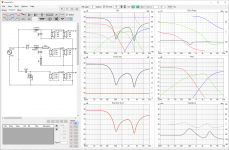
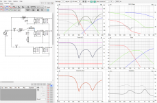
Anyway, I did the most incredibly rough sim with not much idea how the drivers behave. Was mostly interested in keeping impedance sensible.
Curiously I got negative polarity on the tweeters. Adding a shunt 0.3mH after the 3uF looks like harmless fun. Impedance stays above 6 ohms whilst dropping tweeter level 12dB at 1kHz. 3.5kHz crossover. Third order seemed to do too much to phase and amplitude, and would be unpredictable.
Can't recommend messing with the mid filter. Looks alright, and Roy Allison must have known what he was doing.
Must correct the image of the IC20 speaker I showed earlier. The Allison Two is 3 single drivers on each side WMT, not WMTTM.
I think you must need to adjust acoustic centres for time and phase offset here...
Anyway, I did the most incredibly rough sim with not much idea how the drivers behave. Was mostly interested in keeping impedance sensible.
Curiously I got negative polarity on the tweeters. Adding a shunt 0.3mH after the 3uF looks like harmless fun. Impedance stays above 6 ohms whilst dropping tweeter level 12dB at 1kHz. 3.5kHz crossover. Third order seemed to do too much to phase and amplitude, and would be unpredictable.
Can't recommend messing with the mid filter. Looks alright, and Roy Allison must have known what he was doing.
Must correct the image of the IC20 speaker I showed earlier. The Allison Two is 3 single drivers on each side WMT, not WMTTM.
What's relevant regarding Vituix is that Ryeno is just comparing values to see how much difference there may be, this is good. However real responses are not being used so there's no point trying to be precise... just learn how to make differences by looking and then listening to what this does.
- Home
- Loudspeakers
- Multi-Way
- Allison One or Two Speaker Crossover upgrade - ideas wanted