Why not?
Dual mount possible, radial or axial.
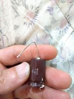
I am quite certain 1 of the radial pins is connected to case, DID you check for continuity with th main case one? 😀
Pinout might also indicate a dual capacitor, but in this particular case labelling does not support that.
Very popular in the old Tube era.


Grandpa 😉 :
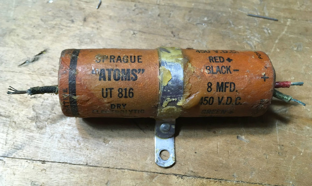
Similar but with tabs instead of wires:

Dual mount possible, radial or axial.
I am quite certain 1 of the radial pins is connected to case, DID you check for continuity with th main case one? 😀
Pinout might also indicate a dual capacitor, but in this particular case labelling does not support that.
Very popular in the old Tube era.
Grandpa 😉 :
Similar but with tabs instead of wires:
Last edited:
I was trying to replace the old part with something more modern. Can I pair 2 capacitors?
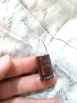
The value is 470uf 50v.
The value is 470uf 50v.
Do you have a capacitance meter?
Many multimeters incorporate one.
Check between each radial leg and case , and between radial legs.
You might have 1 or 2 capacitors there, meter will tell.
Many multimeters incorporate one.
Check between each radial leg and case , and between radial legs.
You might have 1 or 2 capacitors there, meter will tell.
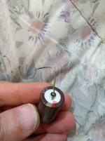
Oh I see.... that would make sense at the schematic doesn't show 2 capacitors and the top pin is connected to the audio input ground.
So its to shield the capacitor?
So its to shield the capacitor?
Rotate cap and post full labelling.I was trying to replace the old part with something more modern. Can I pair 2 capacitors?
The value is 470uf 50v.
What does it say?
Do you have + or - signs?
Any signs stamped on the rubber seal where radial legs exit?
That woluld be real old style but not impossible.
Last edited:
How about giving us the Pioneer model number and let those of us curious enough to want to research it, have some way of checking what it really is. My suggestion is a non-polarised signal cap with isolated, grounded case acting as a shield- just because its about the only reason anyone would have for this type of product in an audio amplifier.
It is a capacitransistor! LOL
I measured it with my multimeter the pins at the bottom and top there is only 0.8uf of capacitance between each leg and only between the bottom pins around 470uf.
I measured many time, it seems the top is just for shielding...?
I measured it with my multimeter the pins at the bottom and top there is only 0.8uf of capacitance between each leg and only between the bottom pins around 470uf.
I measured many time, it seems the top is just for shielding...?

I think this was made to lay down flat, but still have radial leads. The mystery lead
just keeps the capacitor down on the board.
just keeps the capacitor down on the board.
Well, I must admit that I have never seen such capacitor in my electronics life. Probably Nippon Chemi-Con made them just for Pioneer. 
Edit: clearly it's not bipolar. The minus markings are there.
Edit: clearly it's not bipolar. The minus markings are there.
Last edited:
The top pin connects to pin 1 Ground from the pre to the poweramp section. It was also glued down lol. Is it even that of an important cap?
Noise shielding, in the old days the shield was a grounding method.
Note there is a dotted cross on the schematic next to it, so it is special, to be noted, and so on. There may be details about it in the parts list in the service manual.
You might remember that on TV tuners, there was a shield to protect from stray signals, in the form of a metal housing which was connected to ground.
This could be similar, possibly connected to supply ground with some isolation device, our supply negative through a resistor, coil, somehow grounding the device to protect from stray signals.
We used to see small through hole capacitors for RF use, there was a round ring which was to be soldered to the hole in the shield it passed through.
You can put a thick copper foil, or anything similar as a shield, after replacing, if needed, if you use a standard capacitor, connect the shield to ground.
If the chassis is metal, and a three wire connection with earth is available, then ground the chassis, put a standard capacitor, i don't think shielding will be needed then.
A similar method is followed now, one sees this in multi layer PCBs, one layer being used as a ground plane.
Last edited:
- Home
- Amplifiers
- Solid State
- What kind of Capacitor is this?