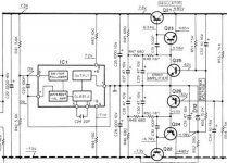
It seems IC1 should be in the schematic as it creates a virtual GND. What is the type number?
I think a design with CLC filtering and both LT3045 and LT3094 can be made way smaller and with less noise as well.
I think a design with CLC filtering and both LT3045 and LT3094 can be made way smaller and with less noise as well.
Last edited:
Yes it may be so but rebuilding the PSU on perfboard seems futile in 2021. Did you see the necessity for IC1?
That is strange reasoning as no one said it is bad. Bad is the opposite of best. Secondly one can not state it is like new after 42 years because its is not like that with electronics (or humans as I find out myself 😉). The question is how the performance is compared to a modern PSU. Copying/rebuilding old schematics is nostalgia. Since you showed a perfboard design I got the impression you wanted to use this PSU for other purposes which seems futile with modern regulators and their stellar specifications. At the end of the analog era we get the best linear regulators 🙂
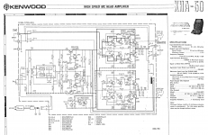
BTW I just looked up the schematic of KHA50 and I would use best available quality caps for the 4 pieces 100 µF 10V at the inputs. I have searched my stock of SAL caps because of another thread and if you like I can sponsor replacement of the input caps with superb 128 SAL RPM solid aluminium caps. I have those in 47 µF 6.3V and 68 µf 6.3V. Since these tolerate almost non polar application and have ultra low leakage I think they will outperform the current parts. Well I am sure of that, certainly if the original parts are still there. I hope the tube guys see the schematic only to conclude Kenwood used a "shorting to GND" muting relay 42 years ago 😀 For many this is too modern even today in 2021.
The output sections seems unusual with 2 caps in series. In the complete schematic it is clear that IC1 creates virtual GND and keeps symmetry.
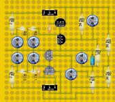
Attachments
Last edited:
yes it uses some good features, even compared with today products.
I see no need to replace the caps, since the device is still so quiet as it is. I can not hear a difference in noise compared to a MC step-up. So, when you can find one, do not hesitate to try it.
So my thoughts were: when it works so good in a MC prepre, it will also work fine in a
MM riaa pre. I have a habit to use abnormally ideas , I believe this is what makes diy
more satisfying as I understand it.
Thanks for willing to sponsor me with caps, but in the moment I see no
time slot for building the breadboard, since I have first other projects waiting to finish.
The properties of the caps are crucial in a design like this. That is why many avoided large value electrolytic caps in similar circuits as leakage was a real issue then. Old geezers like me will remember the orange electrolytic caps with the letters LL (Low Leakage) stamped on them that were used in circuits where leakage could not be tolerated. As we know some capacitors types have improved tremendously over time. Rebuilding the circuit with old parts for a MM RIAA pre can be done but I guess "good enough" can be bettered by "best" with todays cherry picked parts. Best seems the goal to go for when DIYing as the price difference between "good enough" and "best possible" is not that shocking. Availability of modern parts is also not an issue. Using older parts with sometimes magical properties is often an attack on the wallet as well.
Anyway, let me know when you want to get the best out of it. I left turntable stuff in the eighties already but I like analog design nevertheless as I think it demands way more skills.
Anyway, let me know when you want to get the best out of it. I left turntable stuff in the eighties already but I like analog design nevertheless as I think it demands way more skills.
Last edited:
You omitted IC1 too (if you will use a single PSU feeding the circuit). But that is not what I mean, I mean the original circuit seems to have some errors.
Tip: try to use a PCB design program for best results of circuits. It may seem a too steep learning curve but it is rewarding.
Tip: try to use a PCB design program for best results of circuits. It may seem a too steep learning curve but it is rewarding.
Last edited:
I do not need a virtual ground for my purpose, because I intend to use a
double AC supply which gives me a ground, or a delon quadrupler
which makes from a single AC supply a symmetrical voltage, when the middle voltage is used as ground. Thatsway I do not show it.
By the way, lochmaster is a layout program, similar to sprint layout, which I use for my printed circuit board projects. Yesterday, I made a layout for a 1978/7 elektor cascode 4 transistor phono circuit, of which I curious how it compares to other phono amplifiers. If there is any interest, I can show it in a other section here in the forum
Strip board/perfboard is not what is meant with PCB design.
Some newer transistor types have better properties than the more known ones including those that are known as "low noise" that are not low noise at all. For instance BC550/560 that are noisier than the types that were supposed to be noisy 😀 Many have chosen these only because of datasheet remarks that they are "low noise" or from hearsay.
Where have all the Low Noise Transistors Gone?
Last edited:
for my purpose, the BC550/BC560 are sufficient, I have them in a drawer, and I use them often in audio projects.
So, what else errors are in the KHA50 schematic?
So, what else errors are in the KHA50 schematic?
...
So, what else errors are in the KHA50 schematic?
R13, VR1
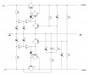
the dot between the figures is not always visible, I had it to sort out when drawing the clean power supply
- Home
- Amplifiers
- Power Supplies
- the power supply of a Kenwood KHA50 MC prepre