Hello everyone,
Picked up a Harmon Kardon F-3 / FA-3000X / XAM Mark IV (EJ Korvette's) yesterday. According to the previous owner it worked - but needed a lot of work. It is certainly filthy.
A visual inspection revealed a blown 32uf electrolytic and a poorly soldered pair of 120 ohm 5W resistors in series that had broken free from the bias potentiometer. Wired to ground.
Questions to all the more knowledgeable experts here:
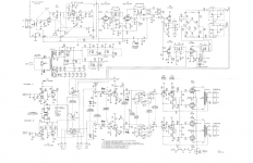
1. The schematic does not have either the 240ohm 5W resistor or the 32uf electrolytic. In the schematic it is wired straight to the pre-amp heaters and then to ground via a capacitor. Any ideas why resistor and capacitor would have been added?
2. The receiver would have originally had 7408 power amplifier tubes. They now have 6V6GT tubes. I understand they are direct replacements. Is it possible that the resistor/capacitor modifaction was done in order to accept the 6v6 tubes?


Thank you,
ikonw8
Picked up a Harmon Kardon F-3 / FA-3000X / XAM Mark IV (EJ Korvette's) yesterday. According to the previous owner it worked - but needed a lot of work. It is certainly filthy.
A visual inspection revealed a blown 32uf electrolytic and a poorly soldered pair of 120 ohm 5W resistors in series that had broken free from the bias potentiometer. Wired to ground.
Questions to all the more knowledgeable experts here:
1. The schematic does not have either the 240ohm 5W resistor or the 32uf electrolytic. In the schematic it is wired straight to the pre-amp heaters and then to ground via a capacitor. Any ideas why resistor and capacitor would have been added?
2. The receiver would have originally had 7408 power amplifier tubes. They now have 6V6GT tubes. I understand they are direct replacements. Is it possible that the resistor/capacitor modifaction was done in order to accept the 6v6 tubes?
Thank you,
ikonw8
Last edited:
Yes, the 6V6 is an OK substitute for the 7408.
Perhaps the factory "Cheap Charlie" DC heaters that used said heaters as the O/P tube cathode resistance was reworked.
Perhaps the factory "Cheap Charlie" DC heaters that used said heaters as the O/P tube cathode resistance was reworked.
Thank you Eli. Duncan2 - here you go. I found it on AK.
Error | Audiokarma Home Audio Stereo Discussion Forums
Error | Audiokarma Home Audio Stereo Discussion Forums
ikonw8,
Your schematic link in Post # 4:
Those who are registered with Audiokarma can read that schematic.
Those who are not registered with Audiokarma can not read that schematic.
(I can not read that schematic).
Karl Barth once suggested ["Barth's Distinction"] that you can divide everyone into two groups:
Group 1: those who divide people into two groups.
Group 2: those who do not divide people into two groups.
See if the tube heaters are still wired as in the schematic or if the resistors are used to replace them in the grounding scheme. The cap might be the cathode bypass cap as seen in the schematic.
I liked that piece of intellectual philosophy and yes I wasn't expecting that --join us--or else !
I am used to Hi-Fi Engine where you are greeted in a less pompous tone .
I am used to Hi-Fi Engine where you are greeted in a less pompous tone .
Thank you Eli - a gentleman.
I see what you mean --unusual to bias the cathodes that way does provide balance adjustment but I also would convert the cathode circuit as who is going to run two output tubes with a large difference in gain ( gm ) better changing them long before that.
I see what you mean --unusual to bias the cathodes that way does provide balance adjustment but I also would convert the cathode circuit as who is going to run two output tubes with a large difference in gain ( gm ) better changing them long before that.
Last edited:
I suppose my question is, do I remove the addition resistors and capacitors that were added to the circuit so that I return the rexeiver to stock (and match the schematic), or leave them in?
Last edited:
Personally ?-- I would leave them in ,I don't like heater circuits used to cathode bias output tubes .
Do you want to improve the performance of the power amplifier section? . . .
As long as you are going to use an RC self bias network, then use 4 Rs and 4 Cs, and then the individually self biased output tubes will match plate currents much better.
The small laminations of the output transformers will love you for that . . .
No early core saturation.
You will have plenty of room for 4Rs and 4Cs, if you take out the phono preamp.
Then power V7, the line level input tube from the 6.3VAC filament winding.
Use an outboard phono preamp, if vinyl is your thing.
Otherwise, just restore the receiver to original circuit, and live with that original level of performance.
Just my opinion (I used to own an HK A300 Amplifier, the same except no tuner).
Last edited:
I loathe the "Cheap Charley" technique. For starters, a very tightly matched quartet of O/P tubes is needed, as the bias network is common to all 4. Then there is the unpleasant possibility of the music signal modulating the preamp tubes' heater current.
Use an outboard phono preamp, if vinyl is your thing.
Or fabricate an external, regulated, 12 VDC supply for those heaters. The difficulty level is very low.
Permanent configuration of the low level, mag. preamp to RIAA only is also appropriate. Tape head capability is passe and switches in mV. level circuitry is a bad idea.
Thank you everyone for your input on this so far.
@Eli - I think I understand the design of original circuit and the benefit of the modification. I will leave the resistor and capacitor in for now. Also, great idea on bypassing the switch for the phono pre-amp! Totally agree.
@Eli - I think I understand the design of original circuit and the benefit of the modification. I will leave the resistor and capacitor in for now. Also, great idea on bypassing the switch for the phono pre-amp! Totally agree.
@Duncan - makes sense to leave them in for now.
@6A3Summer - I like your idea, I may give that a try.
I have repaired the bad solder joints and replaced the blown capacitor. I think the failure here was a cold solder joint at the resistor. I powered it up on an isolation transformer and variac.
The receiver works, aside from scratchy controls and a 60hz hum.
The hum is present at 0 volume and does not increase when the volume is raised. Also, no hum when I monitor the tape output. Two of the filter capacitors have been replaced at some time, but there are two more that I suspect are getting tired. I think I will go after them next.
I realized that 60hz hum was not likely filter capacitors, so before I started on those, I did some more probing around with a chopstick to inspect the wiring.
I located some poorly soldered 12AX7 heater wires that were picking up noise. Moving and lifiting the heater wires around slightly eliminated the hum.
Also found a cold solder joint on the loudness pot, and secured that too.
Hum gone.
I located some poorly soldered 12AX7 heater wires that were picking up noise. Moving and lifiting the heater wires around slightly eliminated the hum.
Also found a cold solder joint on the loudness pot, and secured that too.
Hum gone.
Good for you Ikonw8 only by working on something do you learn the practical aspects of a piece of audio equipment rather than just theory from a book-being taught or from a website it helps to learn about unusual faults that aren't normally be mentioned.
- Home
- Amplifiers
- Tubes / Valves
- Harman Kardon F-3/FA-3000X/XAM-3B