Connecting a preamp with RCA outputs to a Yamaha P220 power amp with XLR inputs.
The Yamaha doesn't possess, apparently, genuinely 'balanced' inputs.
With regard to soldering the lugs onto an interconnect, a couple of questions:
On the XLR plug...
Positive is soldered to pin 2,
Ground is soldered to pin 1,
Braided copper shielding is soldered to pin 3. Pin 1 and 3 are connected with a short soldered wire.
Question 1.
Is this wiring correct?
Question 2.
On the end with the RCA plug the positive lead is soldered to the pin but ...should both the shielding copper braiding and the ground wire get soldered together onto the ‘sleeve’ part of the RCA plug? (Or should the copper braiding be left unattached to the sleeve?)
Is that a P2200?
What is the preamp? Is is capable of generating the 1.23v needed to push this amp to full output?
The only way I have ever done this is RCA center pin to XLR pin2, RCA gnd to XLR pin 1, and in those cases there is no other conductor in the cable so the shield braid is the ground. This has never produced any noise. I have had issues with cables picking up noise when XLR pin 2 and 3 are tied together or when a second conductor and the shield are tied together at both ends. Much depends on the RF environment you live in and the way grounds are handled with your specific equipment, some experimentation may be necessary.
.should both the shielding copper braiding and the ground wire get soldered together onto the ‘sleeve’ part of the RCA plug
I presume You are using mic cable (2 conductors & braid)
The RCA sleeve part is Your signal ground. Tip is Your HOT.
RCA Pin (1st conductor) goes to XLR pin 2 (HOT)
RCA Sleeve (2nd conductor & braid) go to XLR pins 1 & 3 (COLD & GROUND).
Braids are Your "Faraday cages" so should go always to XLR pin 1 (Chassis ground).
Unless there is a ground loop it should be connected on both sides.
Check RANE's paper about the "pin 1 dilemma"
For the inverse situation, XLR to RCA, COLD output should be floating in order not to stress the output op-amps by the short, but I have done it many times without issues.
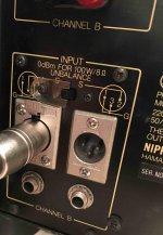
Service manual shows "pin jacks" low on the rear.
Otherwise: XLR pin 2 is "hot", pins 3 and 1 are cold.
Otherwise: XLR pin 2 is "hot", pins 3 and 1 are cold.
Thanks guys, very helpful and clear, I'm nearly there but want to double check..
Correct, I’m using Mogami microphone cable that has a wrapping of braided copper shielding.
So, just to confirm, this shielding should be attached to the plugs at either end.
On the RCA plug: 2nd conductor & braid should be attached to sleeve.
At the XLR plug: 2nd conductor & braid should be attached to pin 1. Pin 1 is then joined to Pin 3.
Correct?
O boy..
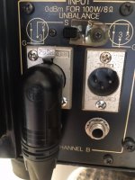
So, given the way that this XLR has been wired (pin 2 hot), should it be plugged into this socket and should the switch be in the position shown in this photo?
Previously I used a "Hosa GXR-135 Adaptor XLR male to RCA” that has pin 3 as hot and pin 1 as ground and it worked perfectly well.
Plugged in the newly soldered XLR and there’s no signal or sound coming through.
I’m sure it’s an obvious mistake so please be kind...
Attachments
that has pin 3 as hot and pin 1 as ground and it worked perfectly well.
Your speaker cones were working in anti-phase.
Positive pressure on mic, cone goes inwards speaker. Should go outwards.
Your ear can't distinguish signal phase.
It only matters if there is more than one speaker, speakers in anti-phase cancel the others in phase. Put speakers close together and invert one of the channels and You will notice overall volume decreasing.
I presume this is a phase selection switch. So Switch it to the right (Standard is HOT signal on XLR pin 2).
Hmm...
That’s interesting, ..unfortunately.
Moved the switch on each channel.
Testing one cable (and checking functionality on Channels B’s output XLR socket) there was a signal present and sound came out of the speaker connected to the Yamaha P2200 with volume pot at max but when the preamp is turned up a little the sound starts to distort, especially noticeable in the lower/bass range.
Plugging the same cable into Channel A, no sound comes through and the meter needle doesn’t move at all.
This didn’t happen at all when I simply used a Hosa RCA to XLR adapter plug.
Then plugged the XLR back into Channel B and there’s no signal or sound output coming through, rechecked Channel A and still no sound.
About to delve back into the XLR plug. But what’s probably the best thing to change?
Thanks PRR, may just be the best advice ever..
But I've bought these lovely Neutrik, nice-spec-gold-pinned-right-angle-XLR's and I want to use them.
Also.. I'm dreadfully short of space behind the amp, the front rubber feet are right on the edge of the shelf..
But I've bought these lovely Neutrik, nice-spec-gold-pinned-right-angle-XLR's and I want to use them.
Also.. I'm dreadfully short of space behind the amp, the front rubber feet are right on the edge of the shelf..
Oops, I haven't yet changed the soldering in the XLR!
So, I should now "connect the 'SIGNAL' to pin 3."(So the RCA 'pin' will now be connected to the XLR pin 3.)
- Then to which pin should the 'second cable' be connected?
- To which pin should the 'braided shield' be connected?
And should Pin 1 and Pin 2 be connected together within the XLR plug?
So, I should now "connect the 'SIGNAL' to pin 3."(So the RCA 'pin' will now be connected to the XLR pin 3.)
- Then to which pin should the 'second cable' be connected?
- To which pin should the 'braided shield' be connected?
And should Pin 1 and Pin 2 be connected together within the XLR plug?
Thanks everyone for your help on this, here’s an update..
So wiring a male XLR plug, the following arrangement is working for me.
No audible noise or hum.
XLR plug:
Pin 3 is hot.
Pin 1 is connected to both the ground wire and the copper braided shielding.
Inside the plug, Pin 1 has a short wire connecting it to Pin 2.
RCA plug:
Pin is hot.
Sleeve is connected to both the ground wire and the copper braided shielding.
Slide switch is pushed to the left on both channels.
Your's is the way the drawing shows for the left handed XLR receptacle. And it's a rather unusual one. Even in an unbalanced XLR connection the hot wire is usually assigned to pin 2 (XLR teardown: 1 = Xreen, 2 = Life, 3 = Return), according to the right handed receptacle drawing.
Best regards!
Edit: I don't see that much use of this switch. What else does it do than switching the related recptacle to the amp circuitry? Why not just leave the unused input open? Who knows?
Best regards!
Edit: I don't see that much use of this switch. What else does it do than switching the related recptacle to the amp circuitry? Why not just leave the unused input open? Who knows?
Last edited:
- Home
- Amplifiers
- Solid State
- XLR/RCA plugs - How to wire connects?