The Mrs has just bought a Cricut Joy, a small plotter/cutter that can do vinyl. A bit cumbersome to load up a design but I just tried a first print of a svg file. Almost successful..

There’s obviously a few gotchas importing svg files - so anyone else use a vinyl cutter?
There’s obviously a few gotchas importing svg files - so anyone else use a vinyl cutter?
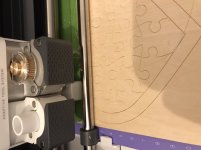
Well attempt #2 failed with an optimised past (ie reduction of complexity).
It got further but (a) it drew big circles across the entire thing and (b) the shapes for the cutout holes were connected via lines (what would be cuts thus not suitable).
I've now been banned from trying PCBs on it - only other way is to render a image and try that.. which I know would work but it may have pixel sharp edges..
Certain Cricut models at topvinylcutters can cut everything you can make as an EPS file, but you'll need to have a cartridge mounted. It doesn't matter which cartridge you use; all that matters is that you have something in there. For a long time, I've been cutting easy things with a Cricut. I'm not sure what model it is, but it's 24" tall and has a USB port on the back.
To add more detail to this.
I bought the Mrs a Cricut Maker for her Xmas present, previously she’s been using the cricut joy for a while.
I tried the same svg file output that failed a few posts back - the same problem exists (it can render the image correctly but the layering sees the white centre of the pcb holes as a different colour.
I will try a postscript to see if the software handles it. It’s certainly capable of cutting thick materials and plotting quite accurately after it’s been calibrated. The maker has a motorised blade rotation as well which it uses rather than relying on the direction of the cut - that makes tear outs less of a problem
Attachments
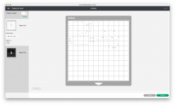
I've been playing - it seems Cricut design space (the app) can also import DXF which it does a far better job of than SVG.
I have got the the point where you can see the holes on the prepare screen - it helps taking the drilling DXF and then using that to create the holes by splicing the the drilling and the top layer together. "Splicing" is Cricut's terminology for cutting one layer out of the other. Too late now for more playing bit seems that it could be possible with alot of messing about. You'll also need to "weld" the images so the pieces of the images are kept together in the correct layout.
I have got the the point where you can see the holes on the prepare screen - it helps taking the drilling DXF and then using that to create the holes by splicing the the drilling and the top layer together. "Splicing" is Cricut's terminology for cutting one layer out of the other. Too late now for more playing bit seems that it could be possible with alot of messing about. You'll also need to "weld" the images so the pieces of the images are kept together in the correct layout.
Attachments
Cool new technique,please keep us updated (success and failure, both help 🙂 )
Show etched PCBs when you have some.
As a side note, I would not even TRY to have a mechanically cutting blade to put tiny component leg holes there (1mm or thinner).
In fact, some PCB software packages do not even draw them either, go figure, just draw the pad and tell drill machine hole center coordinates and which drill diameter to use.
In my own PCBs, drilled on a stand but by hand, I universally put a generic 28 mil hole just to guide conventional HSS steel drill tip, which is long and flexible; when using high speed carbide tipped PCB drills don´t even bother.
In fact, if coordinates and etched surface hole do not agree, I fear cracking carbide drill, go figure, because it will try to go there.
- Home
- Design & Build
- Construction Tips
- Vinyl printers PCB