Amp came In with blown outputs and driver ic’s .
I noticed on the 47mh inductors the voltage jumps all over the place there is no steady voltage it will start at rail voltage then bounce down to 70 volts then back up and continue to cycle like this .
Any ideas on what might cause this ?
I noticed on the 47mh inductors the voltage jumps all over the place there is no steady voltage it will start at rail voltage then bounce down to 70 volts then back up and continue to cycle like this .
Any ideas on what might cause this ?
Attachments
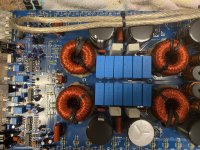
There are multiple circuits that use the 47uH inductors. Which pins of the driver board are the inductors connected to?
Pin 1,10,20,29 are the pins the inductors connect to that the voltage is all over the place .
I also notice the erratic voltage on the collector of the D1302 muting transistor
I also notice the erratic voltage on the collector of the D1302 muting transistor
With the D1302 removed it fixes the voltage issue .
Next question is the split second I supply remote voltage to the amp the relays engage there is no delay .
As soon as I supply remote voltage the relays engage then the amp itself has the initial startup. Is this normal ? First amp ive ever seen do this usually there is a delay before the relays engage
The relays should have a delay. We can deal with that later.
If you drive a signal into the amp, do you have signal on all low-side gates?
What's the DC voltage on all 3 terminals of the 1302?
If you drive a signal into the amp, do you have signal on all low-side gates?
What's the DC voltage on all 3 terminals of the 1302?
Are you sure that you have 0v on the collector?
I would also expect a lower voltage on the emitter than the base.
Measure again with the black probe on the negative rail.
I would also expect a lower voltage on the emitter than the base.
Measure again with the black probe on the negative rail.
I placed the black meter probe on the rail caps ground terminal when I took the measurements .
Where do I place the meter probe for rail ground ?
Where do I place the meter probe for rail ground ?
One of the rail cap terminals is ground.
Place the black probe on either on the output of the negative rectifier or on the shunt resistors.
Place the black probe on either on the output of the negative rectifier or on the shunt resistors.
Emitter:0.00
Collector:0.00
Base:0.00
This is with the black probe on the output leg of the negative rectifier.
And the D1302 still removed from circuit
Collector:0.00
Base:0.00
This is with the black probe on the output leg of the negative rectifier.
And the D1302 still removed from circuit
Back to this amp .
I put a new D1302 in the amp and the pulsing voltages came back .
Does the audio driver board have to be on circuit when testing the voltages on the D1302 ?
I put a new D1302 in the amp and the pulsing voltages came back .
Does the audio driver board have to be on circuit when testing the voltages on the D1302 ?
Ok I figured out the pulsing voltage issue .
Now the problem is as soon as I apply remote voltage the relays engage before the initial power up .
Any ideas on what to check ?
Now the problem is as soon as I apply remote voltage the relays engage before the initial power up .
Any ideas on what to check ?
- Home
- General Interest
- Car Audio
- DC Audio 9.0K