HI folks, This is a reverse polarity damage ,
All the fuses on one side (f100-f107) are blown
Fet's seems to have survived ,
there is some exploded caps but prob from before this reverse polarity accident happen.
Board is covered in some form of liquid,
There is no shorts between the positive and negative terminals.
Might have a good outcome, ( well replacing them fuses is a big job 🙂 )
Any pointers, etc, you guys have a eye for this stuff, i'm merely a beginner.
will keep updated and will fallow instructions if any are given.
Many thanx.
Last edited:
In the future, please post the images to this thread so that they will remain with the thread, even if you delete the file from your server. You'll have to reduce the resolution from what you posted in the zip file.
You have two MP3 files in with the zip file.
The liquid is electrolyte from the vented capacitors. The electrolyte is both conductive and corrosive and you must remove ALL of it.
I don't think that this is RP damage. RP would have destroyed the rectifiers D102 and D152 or blown the ATC fuses. The damage is beyond those diodes and would have been protected.
If you have to remove the transformer, ChipQuik will probably help.
apologies about the photos, tried uploading here, but size too big, i'll resize , and try again,
i most definitely have to remove the 2 transformers to replaces fuses, i started and couldnt even remove the solder of one leg 🙂 so that will need rethinking I'll see that ChipQuik , ty Sir
i most definitely have to remove the 2 transformers to replaces fuses, i started and couldnt even remove the solder of one leg 🙂 so that will need rethinking I'll see that ChipQuik , ty Sir
i use a Weller 80w iron with a big chisel tip that was very inexpensive for transformers and terminals and makes very quick work of those big traces that soak up all the heat from your normal iron. Can also use a heat gun and pre heat the surrounding area so the trace doesn't absorb and dissipate the heat instantly when removing the solder.
Reverse polarity can blow the caps from my experience and not always burn the rp diodes visually. Unfortunately "my experience" was from my doing.
Reverse polarity can blow the caps from my experience and not always burn the rp diodes visually. Unfortunately "my experience" was from my doing.
Hi everyone , still working on this amp, i have a perfectly working Power supply section,
Nothing on the output yet, but after this im hoping,
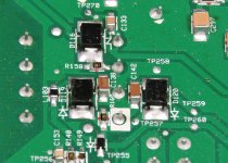
I need the value of R158 , its blown , it's under T107 (smallest of the 7 transformers on the board., i really appreciate the help if posible.
Nothing on the output yet, but after this im hoping,
I need the value of R158 , its blown , it's under T107 (smallest of the 7 transformers on the board., i really appreciate the help if posible.
r168 -2.46K ohm one way, 3M the other way. expected 1ohm
c138- 2ohm
how would i go about checking t107? is that something that would normally fail?
c138- 2ohm
how would i go about checking t107? is that something that would normally fail?
c142 = 2.36k one way, OL the other
r160 or r168, i wasn't sure what last number was, (the 1R0 to the left of the transformer white marked pin )
r160 or r168, i wasn't sure what last number was, (the 1R0 to the left of the transformer white marked pin )
If it doesn't read 1 ohm, it's open.
Do you have an inductance meter?
Please (and this applies to anyone who needs repair help) use your sig line to list all equipment you have, editing it as equipment changes. Include the model numbers. If you can't do this due to being a new member, make a list in the next post.
Top of page, menu USER CP >> EDIT SIGNATURE
Oscilloscope (yes or no)
Multimeter(s)
Type of signal source (grounded RCA shields preferred).
Soldering iron
Desoldering pump
Power supply
2 ohm current limiting resistor (hollow cylindrical ceramic 100w preferred)
Yes I do, I also Added Signature,
Can i wire jump those two 1R0 ohm resistors for testing ) i will replace with propper spec after, if posible.
Can i wire jump those two 1R0 ohm resistors for testing ) i will replace with propper spec after, if posible.
The resistors likely acted as fuses. Do you have any leaded 1/8w 1 ohm resistors?
If you pull the transformer, you should be able to tell if any of the windings are defective. A shorted winding should read an inductance well below the others. If your meter has a 'ringer' mode, that may also be useful.
I wouldn't expect to see any continuity between the primary and secondary windings on the transformer.
The Transformer t107 (has between 26nF and 30nF wherever capacitance could be read (in circuit) and has square waves on 2 of the 4 pins on both sides ( when amp power on (i assume its not broken)) ?
,,powering amp up, its using 1 amp , nothing gets hot, just the usual voltage regulator ic103 (which i strapped a heatsink on it to keep it cool while testing, its working a treat,)
i am Not getting any waves on the output transformers, or on the output fets (irfp4227)
After lots of research i realised ic302 and ic306(CD4093BM) are not the drivers
* The output drivers are ic301 and ic305(marking on chip EZ842(from what i could read)(which works out to be a UC2842), Are Those it? There is no wave of any kind on those 2 chips. (they have 40+voltages on some of the pins ( can do a proper pinout read if you need me to) https://www.ti.com/lit/ds/symlink/u...04081&ref_url=https%3A%2F%2Fwww.google.com%2F
i have tried connecting a 4ohm speaker and feed the RCA's with a sine wave from a signal generator app of 80hz from phone, (btw is feeding a whatever Hz sound from a phone the same as using the Oscilloscope to feed it a wave form? ) in case it only starts the output with load and input on RCA's. still no wave of any kind on output fets anywhere. (they are new and still not shorted)
the output circuitry on this thing is insane and boy did i pick the wrong amp to learn on, but when this will run its a huge achievement .
Last edited:
Those could be the driver ICs. Does the pin configuration match?
What's the DC voltage measured between pins 5 and 7?
This isn't the best to learn on due to having no diagram and not being a popular amp. There are many worse than this.
What's the DC voltage measured between pins 5 and 7?
This isn't the best to learn on due to having no diagram and not being a popular amp. There are many worse than this.
Pin 5 -42.03v black probe on batery negative terminal
Pin 7 -42.03v black probe on batery negative terminal
Same readout if black probe on sub/ outup negative or rca outer shield.
0.635v probes on pins 5 and 7
i should walk away from it for a bit, (Defrag the brain a little and let my PentiumII cpu cool down a bit ) 😀
I do appreciate your time sir.
Pin 7 -42.03v black probe on batery negative terminal
Same readout if black probe on sub/ outup negative or rca outer shield.
0.635v probes on pins 5 and 7
i should walk away from it for a bit, (Defrag the brain a little and let my PentiumII cpu cool down a bit ) 😀
I do appreciate your time sir.
- Home
- General Interest
- Car Audio
- Alpine MRP-M2000 repair project