I want to have an idea of where and how I am going to mount the 2SK180's before I start designing a PCB. The THF-51's and 2SK182es seem to be pretty straight forward but the 2SK180 looks a little wonky to mount. I would love to hear your thoughts and ideas!
Attachments
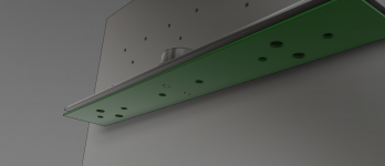
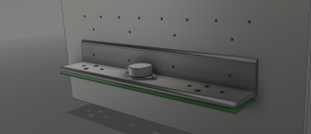
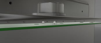
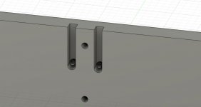
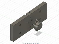
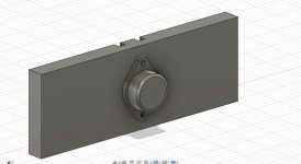
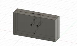
If I use my 2sk180's this is how I'm going to mount them, it allows a good heat path to the heat sink and the PCB's can be located anywhere to suit the case and other components. Connections can be made using high temp cable before the device is screwed onto the mounting plate (insulating pad omitted for clarity). The mounting plate shown is then fitted onto the heat sink with screws to suit.
Attachments

Last edited:
PS.
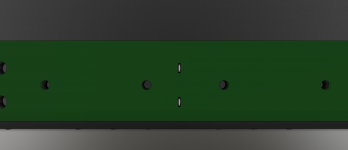
The plate is 14 to 15 mm thick. The slots (and thru holes) are 7mm diameter and the slots are 7mm deep in my example.
The plate is 14 to 15 mm thick. The slots (and thru holes) are 7mm diameter and the slots are 7mm deep in my example.
Last edited:
I don't quite get this. Why not just use a simple thread in the heatsink, like with any other transistor?
Reading and following this with a lot of interest as I have a bunch of 2SK180, 2SK182SE and THF51S laying around for future projects. Please let me know what a set of milled plates would cost in case you have them made.
Bren, rephrase the question. Tokin is 'panel mount' only, and must be connected by drain/source via decent wire.
edit, perhaps his metal machining method allows access to thread wire, and maintain the thickness of the total material. The source connection of an sk180 extends about 12mm or 1/2 inch.
edit, perhaps his metal machining method allows access to thread wire, and maintain the thickness of the total material. The source connection of an sk180 extends about 12mm or 1/2 inch.
Last edited:
Yes, this is possible, but I would not want the devices on the outside of my amp. To me, it spoils the look.
Sometimes a good amp requires the parts to be hidden. Low ego, max enjoyment. Feel free to hide them in the coolest location needed. TO3 can type mount presents that dilemma, esp. at 30+ watts per device. A well-seen 'bracket' is simply eye candy, a worst case and never as effective. In this instance, a 'can' should mate the outside and speak to the inside, hence the form.
Last edited:
In a now old article, Nelson presented his version of a JLH amp (PLH). Now, forget that circuit for a second and scroll to the product. That chassis is a 'can' chassis. Plate aluminum, with rec tube. Perfect for the cans or otherwise. Build to your content. Spray it rustoleum and wet sand to your wish. You can even make that from retail metal (2-4$ lb.) and your crosscut saw. Tap with a drill press and your own imagination.
5 pounds... 17 pounds of aluminum. Its your wish. (IME each 1 lb is good for 10 watts)
The point is, who cares what it looks like. That's what you'd say?
But then you care what it looks like.... so do a good job.
5 pounds... 17 pounds of aluminum. Its your wish. (IME each 1 lb is good for 10 watts)
The point is, who cares what it looks like. That's what you'd say?
But then you care what it looks like.... so do a good job.
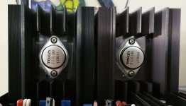
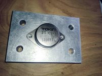
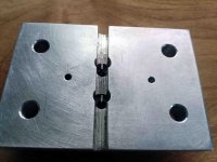
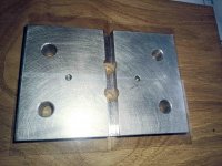
I thought I would post to show a finished article. It's just some bits of 15mm aluminium. I've cut them on a pull saw using a cheap ali cutting saw blade, seemed to work ok even for cutting the wiring slots, (do wear safety glasses as the swarf flies everywhere, and take it fairly slowly). Obviously the blocks can be any size, these are 100mm x 70mm. I intend to directly fix the VFET to the block, uninsulated and then use mica sheets and shouldered screw insulators to mount the block. This hopefully will help with heat transfer. As is usual the VFET is held on with M4 screws, the block to heatsink with M6.
Attachments

Thank you ZM. It could look "Fuglier" if milled, but I was trying to make it in a way that was possible to many others. Just a drill and a saw. (I imagine that a router would do also). What surprises me now is the low cost of Chinese carbide cutting tools.
- Home
- Amplifiers
- Pass Labs
- 2SK180 mounting ideas