Have seen a bunch of videos, read what I could find, fiddled with my o-scope for what feels like hours, and simply cant find a difference on any leg on any K40Y.
Figured Id be smart, and out smart the scope. Built a 4-5 turn coil, put the cap in it, ran every signal I could at 1 volt, 5 volts 15 volts. Anything I could think of to create some emf. No luck...
When I connect my oscilloscope on (without the ground) I easily see the 60 Hz hum surrounding us in the US. Grab the cap, signal goes haywire. Try to some what smooth the results and keep it in the display by adjusting, mark the high and low with cursors and reverse the cap, and I always get the same exact measurement.
The cap's are .47uf. Before I solder them in tomorrow, figured Id ask the experts if there is a better way with basic tools..
Hi, I have never found one end to be different from the other. If the ones you are using have the exposed metal case then you can ground that. A metal strap around it will work fine. I also found that you can solder to them. Just beware not to heat the cap up too much.🙁
I found the metal cans on the K40,42,and 72's acts like a shield making it very hard to determine the outer foil. For sanity sake grab a regular film cap and measure those to be sure you have the scope dialled in properly.
I found this schematic online many years ago, brilliant little device that switches the two connections around every couple of seconds which makes it so much easier to tell the difference, especially for these type of caps where the difference is very subtle. Can't remember where i found the schematic or i would link to the website.
I found this schematic online many years ago, brilliant little device that switches the two connections around every couple of seconds which makes it so much easier to tell the difference, especially for these type of caps where the difference is very subtle. Can't remember where i found the schematic or i would link to the website.
Attachments

Last edited:
Bruce., they had the green coating wish it was that easy!
Mcandmar. Good call on grabbing a film cap, will see if i have one to test.
Mr Carlsons vids are amazing! I will get to that one day, right now I just want my amp back up, so i can start on the Ms-300b upgrades.. i need something in working order at all times!
Mcandmar. Good call on grabbing a film cap, will see if i have one to test.
Mr Carlsons vids are amazing! I will get to that one day, right now I just want my amp back up, so i can start on the Ms-300b upgrades.. i need something in working order at all times!
I simply scrathed off the green paint at a tiny spot and soldered a piece of wire between the metal can and signal GND. Because I found the outer metal can was floating and it could pick up mains hum that was delivered to the innards. (wire not seen on the picture yet)
Shared album - László Császár - Google Photos
Shared album - László Császár - Google Photos
Last edited:
Some info here, without building a specific tester:
Outer foil cap measurement with Hantek 6022BE
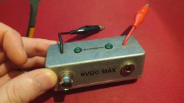
And here is a tester that works automatically and deterministically (and uses a single commodity IC):
ƑƠɭįƠ is a simplistic, yet automatic outer foil tester for capacitors
Outer foil cap measurement with Hantek 6022BE
And here is a tester that works automatically and deterministically (and uses a single commodity IC):
ƑƠɭįƠ is a simplistic, yet automatic outer foil tester for capacitors