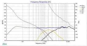
I've been playing around with a 3-way crossover and it's fairly flat above 200 Hz but below that I have 5-6 db of gain @ ~ 60 Hz. I'm using the RS225-8 in a 45l bass reflex. Right now I'm using a 2nd order LR and can't seem to bring it down at all. the phase also looks a bit crazy. I'm a novice so it's not clear what to do next.
Attachments
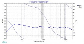
I don't know the sensitivity of your other components, but it looks like you padded down the mid-range and tweeter too much, and that resulted in the woofer being extra sensitive within the system.
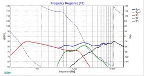
Can you show the graph with all three native driver graphs included?
Can you show the graph with all three native driver graphs included?
Wherever did the notion that a good speaker should be flat FR come from?
If your audio at your chair looks like the FR curve you posted, you'll be very happy. Ask anybody who has cranked up their bass after finishing room EQ by mic. Your curve looks about right top to bottom.
B.
If your audio at your chair looks like the FR curve you posted, you'll be very happy. Ask anybody who has cranked up their bass after finishing room EQ by mic. Your curve looks about right top to bottom.
B.
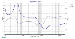
Try LCR in parallel with the woofer to flatten the woofers impedance peak at resonance (with BR flatten the upper peak). Try it in simulator and see what it does in your case. The resistor value can later be used to tune the bass to the room.
I wonder how you got the measurement you posted. Combined near field for low and gated far field for mid and high frequencies?
Or wait, is it data sheet simulation?
Or wait, is it data sheet simulation?
Last edited:
This is a simulation in xsim based on data from PE for the RS225 and fitted graph via VituixCAD and the Morel TM4055. I also did a box design in VC then exported the data for the woofer model. The crossover for the T&M is from Paul Kittinger's Cornetta which is a well respected design. My task has been to find a woofer / crossover that mates well with it and a box of 45l. As suggested, I did try adjusting the T&M lpad to bring up the level, but the graph isn't nearly as smooth. This is the first time I've used these tools - I'm impressive - sure beats doing all the math by hand when I was in grad school 🙂 As suggested, perhaps the bass emphasis will sound good once in a room - this is a actually a rebuild of speakers from the 70's - the first design may give me a updated 70's sound. PFA a graph with more gain in the T&M.
Attachments
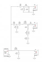
Well, it's about time you reveal your crossover scheme. The chosen slopes are somewhat unusual. And whereas the RS225 can do fine in 45l, I wonder if you picked the vent tuning right.
Plus (brace for the final blow 😉 ) the data you started with are pretty useless. Your enclosure isn't the enclosure the data were acquired from. So the acoustic response won't be the same. Which leaves me to one conclusion: you won't get what you see here.
Plus (brace for the final blow 😉 ) the data you started with are pretty useless. Your enclosure isn't the enclosure the data were acquired from. So the acoustic response won't be the same. Which leaves me to one conclusion: you won't get what you see here.
If it's not clear my now, I don't really know what I'm doing - but I'm having fun playing around at least. My hope was that if I used VituixCAD enclosure tool and generate the frd/zma for use in xsim, it would produce a model that reflect the RS225 in a 45l ported enclosure reasonably closely - is that not a good assumption?
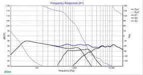
Here's my latest iteration - I adjusted the port and a number of the xo components. Looks like a winner to me - but then again see the first sentence 🙂
Here's my latest iteration - I adjusted the port and a number of the xo components. Looks like a winner to me - but then again see the first sentence 🙂
Attachments
Last edited:
A computer simulation will never show you which values sound best for your speaker.
I've done an LCR bypass myself but the reality was, that those values have been choosen by listening to the speakers sound. The theoretical values were different to the end result which sounded best in my room. This is, because all theory is just a simplified model of the real speaker chassis.
I've done an LCR bypass myself but the reality was, that those values have been choosen by listening to the speakers sound. The theoretical values were different to the end result which sounded best in my room. This is, because all theory is just a simplified model of the real speaker chassis.
What does the simulation of the drive unit in the box look like?
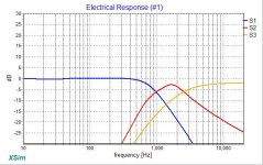
Filter response looks good so its probably a box tuning issue.
Filter response looks good so its probably a box tuning issue.
As markbakk said, unless your enclosure is the same as that in which the measurements were made your result will not be as it should. You really need to match the baffle size and driver positioning on it, internal volume and tuning frequency too.
I've been playing around with a 3-way crossover and it's fairly flat above 200 Hz but below that I have 5-6 db of gain @ ~ 60 Hz. I'm using the RS225-8 in a 45l bass reflex. Right now I'm using a 2nd order LR and can't seem to bring it down at all. the phase also looks a bit crazy. I'm a novice so it's not clear what to do next.
Tune the woofer a lot lower to address the hump.
Wise words.A computer simulation will never show you which values sound best for your speaker.
I've done an LCR bypass myself but the reality was, that those values have been choosen by listening to the speakers sound. The theoretical values were different to the end result which sounded best in my room. This is, because all theory is just a simplified model of the real speaker chassis.
But the error is deeper: the theory tries to predict how microphones hear sound while human hearing isn't quite the same (just like the visual system is not a camera). Human brains have their own strategies for creating perceptions out of a mess of signals from the ears. Being a mess, the brain must process the signals to create coherent sound perceptions.
B.
Isn´t the bump just a room mode?
Try place the speaker somewhere else in the room to see a difference
Try place the speaker somewhere else in the room to see a difference
Here is a screen shot of the enclosure simulation. I do realize that theory / simulation does not capture many nuances and that things may need to be tweaked for real drivers, electronics, room etc. With that said, I'm trying to come up with a decent starting point without it becoming a new career.
This project will likely wind up in a basement 2 channel system at my second home - a bit of an old school system driven by a modified Hafler DH220 (Muscial Concepts) from 30 yrs ago. In my dedicated HT room I use Dirac Live and it made a huge difference -might give a minidsp a shot for this build. My two channel system is CJ tubes with Snell mk.5II speakers and a Velodyne servo sub - still love this combo and will be my reference.
Thanks for all the help and guidance!
- Home
- Loudspeakers
- Multi-Way
- bring down the bass hump