Hello Friends.
I have an Adcom GFP-555 where the power light comes on but there is no sound from any of the outputs.
The output relay does not toggle.
The power LED comes on.
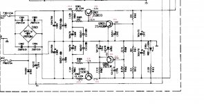
I've obtained the schematic and from what I measure it looks like there is a fault in the power stage.
I've attached the relevant section, my measurements are in red.
Nothing on the board looks burnt.
From looking at the measure points, what would the best course of action be to fix this?
Thanks!
I have an Adcom GFP-555 where the power light comes on but there is no sound from any of the outputs.
The output relay does not toggle.
The power LED comes on.
I've obtained the schematic and from what I measure it looks like there is a fault in the power stage.
I've attached the relevant section, my measurements are in red.
Nothing on the board looks burnt.
From looking at the measure points, what would the best course of action be to fix this?
Thanks!
Attachments
Check both pass BJT,s =Q901/Q902 for faults .if okay then check the base control BJT,s =Q903/Q904 .
I take it +/- 34 Volts is reaching both pass transistors collectors ?
I take it +/- 34 Volts is reaching both pass transistors collectors ?
Have you checked the resistors around q901 /902? They are not getting “turned-on” so you are missing voltages to turn on the next stage of transistors.
If the resistors measure good, then check q901/902, as the next likely thing is one or both are defective.
If the resistors measure good, then check q901/902, as the next likely thing is one or both are defective.
Thanks!
I’ll pull them out tomorrow and check them.
Yes, the +/- 34V reach Q901 and Q902 collectors but go no further...
I’ll pull them out tomorrow and check them.
Yes, the +/- 34V reach Q901 and Q902 collectors but go no further...
Overload (short circuit) at the output of the stabilizer is possible.
Are the output transistors punctured?
Are the output transistors punctured?
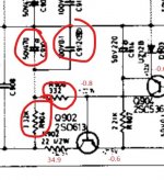
Hazy thinking... what would a short across C910 or C912 do (or an open resistor feeding them).
The positive rail would not come up, the negative would try to rise but just turn on Q903 and clamp the negative output rail to a low value... which you have.
The positive rail would not come up, the negative would try to rise but just turn on Q903 and clamp the negative output rail to a low value... which you have.
Attachments
A fruitful Monday morning saw my first successful electronics repair:
I pulled R's 901-906 and found R904 was opencircuit.
Also pulled Q's 901 and 902 but since they measured the same as each other I figured they were OK.
I daisy chained some resistors together to get the same value as R904 (3.3K) put it all back together and now it works. "Hell aint a bad place to be" sounds real good right now.
Thanks to you all in this forum for inspiration and tips!
Excellent  Fault diagnosis is always about gathering evidence (all the readings you provided) and then doing a bit of piecing together to try an make sense of it.
It might be worth replacing its opposite number in the upper half of the circuit.
Fault diagnosis is always about gathering evidence (all the readings you provided) and then doing a bit of piecing together to try an make sense of it.It might be worth replacing its opposite number in the upper half of the circuit.
Indeed, I now need to source the resistors and I do intend to replace both but seem to end up with a 50 cent shopping basket and $15 delivery fee.
Where do you guys in Melbourne/ Australia shop for electronic bits? I like the service at element14 but two resistors is not really worth the overhead.
3.32k seems also an odd value not in common kits.
Where do you guys in Melbourne/ Australia shop for electronic bits? I like the service at element14 but two resistors is not really worth the overhead.
3.32k seems also an odd value not in common kits.
You can buy a larger quantity of 3.3k and choose according to the measurement results. You can get the desired value from parallel or series connection of resistors (Other resistances).
Last edited:
These are not critical at all and you will find that 3k3, 3k9 or even 4k7 will all work. They play no part in the voltage setting and simply provide the required 'forward bias' for the pass transistors.
If you are fussy put a multi turn preset, 10k, and then set it as per your taste.
what would you adjust it for?
It doesn't set the voltage 🙂
Good to know it’s not got to be super-exact.
Incidentally the good one i pulled out measured to exactly 3.32k ohm, so I thought that it was of relevance.
Incidentally the good one i pulled out measured to exactly 3.32k ohm, so I thought that it was of relevance.
I did try a 10k trumpet but found it impossible even to get the required value.
I can see why 😉
All that resistor does is provide the required base current for the series pass transistor and also (and importantly) it sets the current in the 12 volt Zener which is used as the reference... but the good news is that its not critical. As long as you have 'enough' current it will all work just fine.
- Home
- Amplifiers
- Solid State
- Faulty power supply stage