Hi all, first thanks for helping me out with the phase splitter here in this thread
I was super enthusiast that I got the phase-splitter output swing going to ~35Vpp to drive the output tubes. Now I re-connected the negative feedback and the amplification factor from the first stage pentode dropped from x40 without NFB to x13 with.
And now I do not reach what I wanted on the output tubes / phase splitter
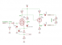
At 2Vpp in Pin 9 gets 26Vpp and Pin 1 has 24 Vpp
The NFB Signal on Pin 3 and 7 is 1.6Vpp
So is this to much ? Normal ? Any suggestion on improving the balance between amplification and negative feedback correction with the 10K resistor? I could add an extra tube stage but that I do not see in other similar simple diagrams and would like to avoid that.
I was super enthusiast that I got the phase-splitter output swing going to ~35Vpp to drive the output tubes. Now I re-connected the negative feedback and the amplification factor from the first stage pentode dropped from x40 without NFB to x13 with.
And now I do not reach what I wanted on the output tubes / phase splitter
At 2Vpp in Pin 9 gets 26Vpp and Pin 1 has 24 Vpp
The NFB Signal on Pin 3 and 7 is 1.6Vpp
So is this to much ? Normal ? Any suggestion on improving the balance between amplification and negative feedback correction with the 10K resistor? I could add an extra tube stage but that I do not see in other similar simple diagrams and would like to avoid that.
Attachments
Connect the common of the output transformer secondary to the audio ground, if it is not already.
The gain of the pentode did not change, you are feeding it an additional signal (feedback from the output)
that cancels some of its input, which is how nfb works.
The question is, with the feedback and an 8R dummy load, do you get the desired output voltage
at the load with a 2V input signal? Normally you would want 2Vrms input for the rated output,
not 2Vpeak to peak (which is around 0.7Vrms). Turn up the input signal, it's expected that the gain
will be much less when adding nfb.
Last edited:
Hi Rayma, thank you for taking the time to answer, Yes I know that I deliberately cancel some input (neg feedback) I'm just surprised / not happy that it cancels so much. from x40 to x 13. I am measuring with an 8R dummy load and I do not get the desired output.
It plays fine but wanted to get closer to the voltage needed to get maximum drive at the output tubes. (No specific reason, just learning and hobbying) without NFB I got very close.
It plays fine but wanted to get closer to the voltage needed to get maximum drive at the output tubes. (No specific reason, just learning and hobbying) without NFB I got very close.
With the feedback and an 8R dummy load, do you get full rated output voltage at the load
with a 2Vrms (5.6V peak to peak) input signal?
with a 2Vrms (5.6V peak to peak) input signal?
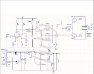
I see you have used a resitor network to bias your phase splitter. This is a bad design as it loads the previous tube too much. Best is to use no capacitor at all (less phase shift) or use at least a bias on the tube itself (no additional connections to ground, as the power rail also acts as ground here, the 680K and 220K are actually in parallel).
Attachments
Last edited:
That schematic is allmost hopeless , the gain of the pentode is
laughable , look at a practical schematic that I made and draw some conclusions .
Input sensitivity for 2x43Vrms is just 170mV of course without negative feedback .
Russian 6F1P was tried and is allmost the same .
laughable , look at a practical schematic that I made and draw some conclusions .
Input sensitivity for 2x43Vrms is just 170mV of course without negative feedback .
Russian 6F1P was tried and is allmost the same .
Attachments
Last edited:
Depanatoru, Lampie519 Thank you 🙂 I'm eager to start adjusting the components and pentode set-up. In my case this is how the board came. I'm very interested in your suggestions and am going for it.
I would like to read up first, can you point me into the direction why the original setup has such poor gain ?
Thank you, I'll feedback the result in a few days.
I would like to read up first, can you point me into the direction why the original setup has such poor gain ?
Thank you, I'll feedback the result in a few days.
Although may not help much with gain the grid leak resistors on the KT88 could be increased to 220k to help with the driver swing.

NFB should be adjusted anyway , if you have the means to do it . For good 1KHz square wave form ( the 100pF capacitor ) and how much do you need ( R17 resistor ) . In general you need just enough for the bandwidth to be sufficiently flat .
That schematic is allmost hopeless , the gain of the pentode is
laughable , look at a practical schematic that I made and draw some conclusions .
Input sensitivity for 2x43Vrms is just 170mV of course without negative feedback .
Russian 6F1P was tried and is allmost the same .
Ordering components now, can you tell me the voltage rating for C2 please ?
Thank you.
Hi Rayma, thank you for taking the time to answer, Yes I know that I deliberately cancel some input (neg feedback) I'm just surprised / not happy that it cancels so much. from x40 to x 13.
If you know the gain without feedback, then you know that the feedback cancels the input voltage to make it just right for the output voltage / no-feedback gain.
Example: no-feedback gain is 100. You add feedback to make the gain 10. Then the difference between the input voltage and the feedback voltage must be output voltage / 100. In this example, the feedback will need to cancel 90% of the input signal to make the result just right to support Vout.
The background is that whatever you do with feedback, the amp itself always continues to operate with its no-feedback gain. The amp doesn't change; you just manipulate the effective input signal (Vin-Vfeedback) to get the right gain.
If you think about it that way, it'll all fall into place!
Jan
Thank you jan.didden, a very clear explanation. All components are ordered, I will be building soon !
Ordering components now, can you tell me the voltage rating for C2 please ?
Thank you.
C2 can be 16V as the voltage across cathode resistor is 1-2V
That schematic is allmost hopeless , the gain of the pentode is
laughable , look at a practical schematic that I made and draw some conclusions .
Input sensitivity for 2x43Vrms is just 170mV of course without negative feedback .
Russian 6F1P was tried and is allmost the same .
Thank you Depanatoru, was this simulation done in ltspice ? Would you mind sharing the file and libs please ?
That schematic is allmost hopeless , the gain of the pentode is
laughable , look at a practical schematic that I made and draw some conclusions .
Input sensitivity for 2x43Vrms is just 170mV of course without negative feedback .
Russian 6F1P was tried and is allmost the same .
Hi Depanatoru, still waiting on components but the model gives a good amplification. Thank you. I did notice in my model that the 6u8a g2 sits at 354 Volt, going to work now. Will check with another tube simulation later today
Thx, stay safe
Attachments
![2021-03-01 09_12_42-LTspice XVII - [TubeAmpIves.asc].png](/community/data/attachments/834/834341-1d7a6459eabce3eac200b60c0b2e5b2b.jpg?hash=HXpkWeq84-)
That is not a simulation , was built and measured in reality . With multiple tubes .
If your model shows no G2 current ( the same voltage across resistor ) then it is wrong .
But after all I don't understand why you do simulations if you have already the circuit build ... it is easier than soldering components ? 😀
If your model shows no G2 current ( the same voltage across resistor ) then it is wrong .
But after all I don't understand why you do simulations if you have already the circuit build ... it is easier than soldering components ? 😀
Last edited:
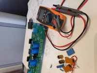
😀 No I'm dismantling and just waiting on components. Ordered a bunch of stuff at the same time, like a test high voltage transformer so I do not need to dismantle the case from the amplifier and wanted to build out my workbench and stock. At the same time I'm rebuilding to go from Kathode bias to negative voltage for the output tubes and a stabilized 350V for the pre-amp tubes. Including a little PCB to replace the original single 6U8 kathode resistor to your 2 resistors set-up and the bypass capacitor with a trimmer to set the NFB. Was just killing time with Spice.
Note, the bit strange layout of the PCB is to make it universal with left/ right on my main PCB so the trimmer always faces forward and both turn in the same direction and to compensate for the left / right direction of GND and Kathode in my set-up.
Thank you for your help I'm also looking forward to have it alive so I can see the output on my scope 😎
Attachments


OK , just pay attention when you build it for auto oscillation or at least tendancy for that . Without NFB sometimes will oscillate itself or only when you touch the input .
That is the purpose of the capacitor on the pentode input . Others use a RC network in anode or capacitor in the grid of triode . But all designs old or new use some kind of HF filter to make it more stable .
So far I don't know the root cause , it's the PCB , the closeness of grid1 pentode with the anode of triode , or internal coupling .
Last edited:
That schematic is allmost hopeless , the gain of the pentode is
laughable , look at a practical schematic that I made and draw some conclusions .
Input sensitivity for 2x43Vrms is just 170mV of course without negative feedback .
Russian 6F1P was tried and is allmost the same .
Depanatoru I have implemented your suggestion an good progress here, Thx!
The open loop gain is now 194 (175mV RMS in , 34VRMS out. ) 0.5Vpp in / 96Vpp out.
So this seems to do the trick 🙂 😀 The DC values are a bit off compared to your set-up. The 6U8 pentode anode is 98.6V instead of 89 and the g2 is 53V instead of 99V and the cathode is at 1.9 V . Is this comparable gain as per your set-up ? Do I need to address the voltage differences ?
- Home
- Amplifiers
- Tubes / Valves
- Need some education - Negative feedback - Too much ?