Hi,
The woofer in question is a car audio woofer, which I asked about in another forum for which I did not get any reply. As it's more technical in nature I'm bringing it here in hopes of general insight of what's going on. At the moment I'm looking at a pair of Sundown U-12s for my next build and it's nice to see that they posted some DAAS32 measurements.
I'm currently designing a series 6th-order and would like to have the best grasp of the driver in terms of TS parameters. Specifically, I design all BP6-series enclosures in Hornresp and I like to work out semi-inductance parameters from the impedance curve but there are some inconsistencies in this trace along with T-S parameters. This is quite critical to know this the most accurately as the impact on a BP6S is unforgiving relative to a simple reflex design.
To look at a specific example, take the U-12 D4 (although the same effect manifests itself on all woofer sizes and coil configurations throughout the U-series lineup). This QTS parameters are also consistent with what Sundown publishes on their site. There are several key features below which I'm not fully understanding:
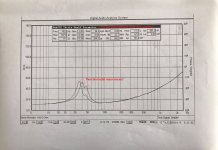
1) The impedance peak for this particular driver is asymmetric and bimodal (40Hz and ~48Hz). This is actually the first time seeing such an effect as though the woofer has two resonant modes... Is there an explanation for this?
-Whether it's just down to smoothing? Not sure about this as the lower peak is too pronounced to be deemed insignificant.
-Whether there is something inherent to the subwoofer design that causes this? Particularly the alarmingly high Rms value of 24.4kg/s (which effectively damps resonance outside of key nodes, like a high-Q effect).
To me it sounds dubious that the subwoofer would have two resonance modes so close together. Ideally you would expect to have a symmetric singular peak and if we were to extrapolate the "ideal" peak it would probably lie ~42-43Hz, rising to an impedance of ~60-70ohms.
2) Ultimately, parameters presented from DAAS32 sweeps are typically bang-on in terms of consistency and yet here there are some strange anomalies.
In terms of TS parameters, there is a strong disconnect between the Fs, VAS and MMS. The Fs cannot be 40Hz with the given VAS and MMS but much higher. I would wager to say that the MMS is realistic for a woofer of this caliber so I'm not sure about the VAS. To me, for the QES/QMS to be agreeable the VAS would have to closer to realm of 20L rather than the published 12.9. I'm wondering if the derived QTS parameters are inconsistent due to the shape of the observed impedance curve or if something else is going on.
3) I'm also questioning the very high Rms...
I've generally not seen such high losses, even in ultra-low QTS, high-MMS, SPL-oriented woofers which are still typically in the realm of 10-12 kg/s. For mid-QTS, mid-MMS woofers I would expect this to be in the range of 4-7 kg/s. Is this value correct?

The woofer in question is a car audio woofer, which I asked about in another forum for which I did not get any reply. As it's more technical in nature I'm bringing it here in hopes of general insight of what's going on. At the moment I'm looking at a pair of Sundown U-12s for my next build and it's nice to see that they posted some DAAS32 measurements.
I'm currently designing a series 6th-order and would like to have the best grasp of the driver in terms of TS parameters. Specifically, I design all BP6-series enclosures in Hornresp and I like to work out semi-inductance parameters from the impedance curve but there are some inconsistencies in this trace along with T-S parameters. This is quite critical to know this the most accurately as the impact on a BP6S is unforgiving relative to a simple reflex design.
To look at a specific example, take the U-12 D4 (although the same effect manifests itself on all woofer sizes and coil configurations throughout the U-series lineup). This QTS parameters are also consistent with what Sundown publishes on their site. There are several key features below which I'm not fully understanding:
1) The impedance peak for this particular driver is asymmetric and bimodal (40Hz and ~48Hz). This is actually the first time seeing such an effect as though the woofer has two resonant modes... Is there an explanation for this?
-Whether it's just down to smoothing? Not sure about this as the lower peak is too pronounced to be deemed insignificant.
-Whether there is something inherent to the subwoofer design that causes this? Particularly the alarmingly high Rms value of 24.4kg/s (which effectively damps resonance outside of key nodes, like a high-Q effect).
To me it sounds dubious that the subwoofer would have two resonance modes so close together. Ideally you would expect to have a symmetric singular peak and if we were to extrapolate the "ideal" peak it would probably lie ~42-43Hz, rising to an impedance of ~60-70ohms.
2) Ultimately, parameters presented from DAAS32 sweeps are typically bang-on in terms of consistency and yet here there are some strange anomalies.
In terms of TS parameters, there is a strong disconnect between the Fs, VAS and MMS. The Fs cannot be 40Hz with the given VAS and MMS but much higher. I would wager to say that the MMS is realistic for a woofer of this caliber so I'm not sure about the VAS. To me, for the QES/QMS to be agreeable the VAS would have to closer to realm of 20L rather than the published 12.9. I'm wondering if the derived QTS parameters are inconsistent due to the shape of the observed impedance curve or if something else is going on.
3) I'm also questioning the very high Rms...
I've generally not seen such high losses, even in ultra-low QTS, high-MMS, SPL-oriented woofers which are still typically in the realm of 10-12 kg/s. For mid-QTS, mid-MMS woofers I would expect this to be in the range of 4-7 kg/s. Is this value correct?
Attachments
Sorry, Sundown Audio has not provided any other information in this regard. It would be interesting to see mechanical displacement is doing at small signal / large signal.
As a side note, this woofer employs a shorting ring as well as a narrow, tall-roll surround which is somewhat unique. Not sure if this could have a significant effect on electro-mechanical behavior.
As a side note, this woofer employs a shorting ring as well as a narrow, tall-roll surround which is somewhat unique. Not sure if this could have a significant effect on electro-mechanical behavior.
Hmm, that's a good point.
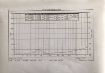
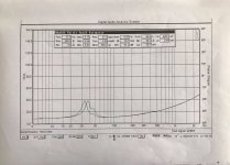
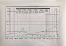
However one thing that is a little interesting is that this node seems to appear on all the sweeps that Sundown conducted; the U10, U15, U18 attached below respectively.


I think it would be a low probability to insecurely mount the woofer in every case. That leads me to believe that this is inherent to this woofer or possibly the DAAS32 system has some problem (however this does not appear in Sundown's published sweeps that I have seen for other lines of their woofers X-series, Z-series, etc...).
However one thing that is a little interesting is that this node seems to appear on all the sweeps that Sundown conducted; the U10, U15, U18 attached below respectively.
I think it would be a low probability to insecurely mount the woofer in every case. That leads me to believe that this is inherent to this woofer or possibly the DAAS32 system has some problem (however this does not appear in Sundown's published sweeps that I have seen for other lines of their woofers X-series, Z-series, etc...).
Attachments
It's possible that the mounting fixture itself has a natural resonance at around 48 Hz.
One time I re-used a baffle that was originally used for testing a 4" mid-woofer, and then cut the hole bigger to mount an 8" woofer on it. I seem to recall that there was some kind of anomaly like that. After adding some stiffeners to the back of the baffle, there was a single hump, with a higher peak.
Some tweeters have damping material added behind the diaphragm, and the impedance around resonance sometimes looks squashed down, or with 2 peaks.
Makes me wonder if there's some kind of mechanical damping at play.
That makes a lot of sense. The effect seems to be the most pronounced on the 12" version of the woofer as the nodes are in such close proximity to one another.
Taking what you said, that the true peak should be higher, I am assuming the resonance of the baffle at 48Hz is resulting in a suppression of the peak at 40Hz. I understand that each impedance is measured separately over the sweep but is it correct in thinking that the second node is "destructively" interfering with the fundamental resonance at 40Hz?
With this line of thought just eyeballing it, it would make sense to me that this particular woofer should peak ~60 ohms, effectively raising the QMS and in turn the Rms. To me it just seems that the mechanical losses of the woofer appear rather high based on the inferred T-S parameters that this sweep dictates.
I am not familiar with the T-S derivation process but I am assuming it uses some form of curve fitting? Given the bimodal curve, it would deviate from the model and this would also explain the inconsistency in the presented T-S parameters (namely the Vas/QTS).
Last edited:
you can test this when you touch the woofer during the measurement to dampen the mechanical vibrations measure with a noise signal to get the graph updated continuously.
What happens in individual tones, not a sweep, manually crept up and down in the area? Kinda cool/weird, but aiso nice TS parameters(, even with that Le.
Hmm, that's a good point.
However one thing that is a little interesting is that this node seems to appear on all the sweeps that Sundown conducted; the U10, U15, U18 attached below respectively.
This suggests an error in their measurement process (like the resonance issue previously mentioned), rather than a unique feature of the woofers. If the additional and unexpected peak in impedance appears around the same frequency in every measurement, then I'd say that it's definitely a measurement process error.
- Home
- Loudspeakers
- Subwoofers
- Cause of two resonances on free-air woofer impedance sweep?