Hi all
what is the topology of dc to dc converter in car amplifier smps section. i know that main topology is isolated transformer but i dont know which one of isolated topolgy used in this.
in i need guidance for transformer selection
what is different between toroidal and EI/ERL
tnx
what is the topology of dc to dc converter in car amplifier smps section. i know that main topology is isolated transformer but i dont know which one of isolated topolgy used in this.
in i need guidance for transformer selection
what is different between toroidal and EI/ERL
tnx
The inquiry lacks application details, but generally high power amps for 12V system uses push-pull topology. Toroidal cores are usually used for low profile and cost, and that the converter does not require galvanic safety isolation.
car smps
tnx bro
im trying to made a smps with tl494 for first time.
for example i want convert 12v to +-20v .
have you any Schematic that work properly or you make it ?
tnx bro
im trying to made a smps with tl494 for first time.
for example i want convert 12v to +-20v .
have you any Schematic that work properly or you make it ?
You do some reading here for possibilites: 700-W Automotive External Audio Amplifier Reference Design PMP11769
Highly Efficient and Compact 100-W Automotive Amplifier Reference Design with Boost Converter PMP9484
Automotive, Four-Channel, Class D Amplifier Reference
Design for Head Unit
https://www.ti.com/solution/automotive-aftermarket-audio-amplifier#technicaldocuments
Highly Efficient and Compact 100-W Automotive Amplifier Reference Design with Boost Converter PMP9484
Automotive, Four-Channel, Class D Amplifier Reference
Design for Head Unit
https://www.ti.com/solution/automotive-aftermarket-audio-amplifier#technicaldocuments
I have seen a Rockford car amp power supply circuit in the forum using 494. It was +/-24V or something. I'm sure it will pop up in a search.
Transformer core material type is important, as is output inductor core type. I recommend using an output inductor.
494 has open collector/emitter outputs. When using the 494 emitter outputs I like to use a J-fet CCS as the load, and a cheap 4403 as the turn off transistor. 🙂
Transformer core material type is important, as is output inductor core type. I recommend using an output inductor.
494 has open collector/emitter outputs. When using the 494 emitter outputs I like to use a J-fet CCS as the load, and a cheap 4403 as the turn off transistor. 🙂
Attachments
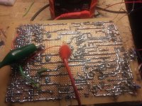
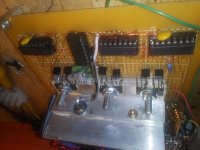
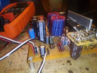
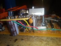
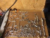
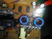
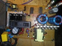
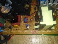
This is a Frankenstien circuit I just made to test a few things and to power a hybrid amp that have. It works pretty good.🙂
Output is two identical isolated separately controlled 30V power output sources. (connected in series at input to amp PCB.)
Pulse by pulse current limiting. (possible with cheap 494 using external components, i. e. a comparator and a latch driving pin 4 (DTC), reset via sawtooth on pin 5. (Ct))
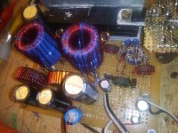
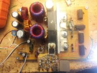
Also, a third baby toroid produces the other voltage sources needed: +50V/-150V @ 10mA (2W); 2 separate isolated 6V @240mA (3W) floating current sources for the valve filaments; and +5V up to 1A (5W) for USB, and Bluetooth receiver. The 200V is regulated by controller and is is driven by 25V secondary and voltage multiplier circuits. Primary is from 9V, regulated from small buck converter from main 12V- 13.8V source.
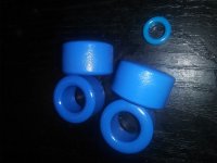
The large power transformer toroids are 25×14.8×15mm, 2 stacked, N87 material (u(i)=2400). Two parallel pri, 2+2 each, 6+6 sec. Fsw=50KHz
The baby toroid transformer is 12.7×7.9×6.35mm, N87, Fsw=145KHz
The inductor cores are powder cores ripped out of old junk. Yellow with white stripe is good here, type 76? I think, with u(i)=76 I think.
Output is two identical isolated separately controlled 30V power output sources. (connected in series at input to amp PCB.)
Pulse by pulse current limiting. (possible with cheap 494 using external components, i. e. a comparator and a latch driving pin 4 (DTC), reset via sawtooth on pin 5. (Ct))
Also, a third baby toroid produces the other voltage sources needed: +50V/-150V @ 10mA (2W); 2 separate isolated 6V @240mA (3W) floating current sources for the valve filaments; and +5V up to 1A (5W) for USB, and Bluetooth receiver. The 200V is regulated by controller and is is driven by 25V secondary and voltage multiplier circuits. Primary is from 9V, regulated from small buck converter from main 12V- 13.8V source.
The large power transformer toroids are 25×14.8×15mm, 2 stacked, N87 material (u(i)=2400). Two parallel pri, 2+2 each, 6+6 sec. Fsw=50KHz
The baby toroid transformer is 12.7×7.9×6.35mm, N87, Fsw=145KHz
The inductor cores are powder cores ripped out of old junk.
Yellow with white stripe is good here, type 76? I think, with u(i)=76 I think.Attachments
-
 20210211_133148_resize_58.jpg166.4 KB · Views: 140
 -
 20210217_134444_resize_67.jpg138.4 KB · Views: 132
 -
 20210217_134432_resize_6.jpg131.6 KB · Views: 129
 -
 20210217_134821_resize_13.jpg97.3 KB · Views: 77
 -
 20210217_134519_resize_35.jpg121.6 KB · Views: 81
 -
 20210217_134600_resize_91.jpg96.4 KB · Views: 148
 -
 20210218_223900_resize_58.jpg83.9 KB · Views: 70
Of course this circuit is for home use though, PCB being drawn in Eagle. The main source is another Frankenstein circuit, off line 12-13.8V high current supply. Also using 494; half bridge with current doubling output. Voltage and current mode control. I had no powder cores on hand for the output inductors so I totally went Frankenstein and cut a 1mm gap in some of the cheap T38 u(i)=10,000 cores I have for CM chokes, changing them to effective u(i) of about 50. Three cores stacked. Quite surprisingly, it works OK.
However this project is venturing off topic, but as a total novice I just wanted to point out some details I've found helpful.🙂
However this project is venturing off topic, but as a total novice I just wanted to point out some details I've found helpful.🙂
Attachments
Last edited:
Edit: As I am a total novice at SMPS, some details I've found out to be helpful are material types and winding techniques of magnetic parts, PCB layout, decpupling, and placement of snubber which is important. Most of which I learned here🙂.
UC3846 is another good candidate for a controller. UC3843/3845 + two comparators and a handful of passives if you feel lucky.
HIP2100 makes a real good half bridge driver and will cut your dissipation at the expense of increased EMI.
HIP2100 makes a real good half bridge driver and will cut your dissipation at the expense of increased EMI.
- Home
- Amplifiers
- Power Supplies
- car amp smps