Hello,
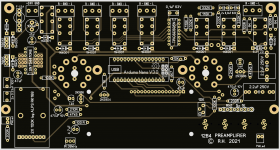
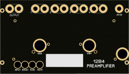
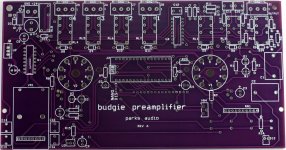
I created the board using a special software based on the schematics and PCB photos that were published !
Shannon Park (diytube.com) Unfortunately, his website and forum have been taken offline,
but I saved everything I need (firmware for the Arduino Nano, for example).
To protect the tubes and fingers, these things are available at aliexpress
Attachments
Last edited:
the top of the original pcb served as a template and that was still relatively easy,
the back was more difficult because there is no decent photo of it
and the back also serves as a ground plane,
so you have to look at the circuit diagram again for each component!
the back was more difficult because there is no decent photo of it
and the back also serves as a ground plane,
so you have to look at the circuit diagram again for each component!
Attachments
Bravo! The designer is a nice chap but when I tried to get hold of the PCBs that was not possible anymore. There was no way of getting the gerbers or a board so the project was more or less killed. It is quite strange that the use of Arduino in good audio circuits is/was not more popular.
While you are at it you can modify some things. If you are interested here are some suggestions and sharp opinions that may be taken with a grain of salt:
- The bass boost and 0/6dB gain relays can be omitted as bass boost does not belong in serious audio and gain is not needed in 99% of cases in this day and age. If gain is needed then one will not switch it with a relay now and then 🙂
- PSU B+ is quite low and could be upped to 48V and included on the board. Only the transformer being a separate part. When SMPS can be avoided many will do so. A separate linear 48V PSU board is also an option. Relays should be the 48V versions then. Challenge is where/how to create the 5V.
- When a linear PSU would be added both the 24V DC for the heaters and a voltage doubler for around 40V B+ are possible with a 20 ... 22V transformer.
- When a multiple secondary windings transformer with the "right" voltages is used things become more easy. Then 100V B+ is an option.
- it can be rewarding to include pads for other types of motorized potentiometers/volume control.
Last edited:
hallo, wohin müssen sie geschickt werden?Mich würde interessieren, wenn Sie mehr Boards machen würden.
Danke
- Home
- Amplifiers
- Tubes / Valves
- Resume Production of Budgie's Preamp PCB 2014