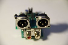
This is my modular AK4490 DAC that I made last year.

I started the design a few years back when I needed an optical SPDIF input for my TDA1541 DAC with tube buffer. Instead of buying something from China I decided to make my own. After all this is do-it-yourself audio, not buy-yourself-chinese-stuff audio.
First I made an integrated SPDIF board with AK4118 and STM32F030. Then I decided to add an AK4490 DAC. Then later AK4137 SRC. Soon I found a need to have a separate STM32F030 control board for other projects so I decided to make this more modular.
Now it contains 5 separate boards:
1. AK4118 receiver with optional AK4137. The board has coax and optical inputs as well as 1 optical output for SPDIF bridging. The board can output I2S via AK4137 or directly from AK4118 so the SRC can be truly bypassed. There is also an additional I2S input to AK4137 for an external USB-to-I2S board.
BTW fittingly the coax spdif input is based on Jocko's design (or rather advice to a fellow member) from 2005.
2. AK4490 board which is more or less according to datasheet with LM4562 as LPF Opamp. LT3042 regulators for VREFL/VREFR.
3. XLR "shield" for balanced output (2 LM4562 opamps).
4. STM32F030 control board with headers for HD44780, encoder, I2C, IR receiver and I/O.
5. Encoder board that has HW debouncers for encoder and switch. No SW debouncing needed.
The DAC can be powered by e.g. a SilentSwitcher with a battery pack (as seen in picture above).
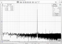
The performance is close to datasheet level. THD is very close to the measurement limit of my setup. Here is the FFT spectrum for 44.1kHz/24bit SPDIF input.

Here are pictures of the DAC board and the XLR "shield".


Now all it needs is a chassis. Also the SW is still work-in-progress. But all in all a very educational project. Buying similar boards ready-made would have been much easier (and a lot cheaper!) but where's the fun in it.
I started the design a few years back when I needed an optical SPDIF input for my TDA1541 DAC with tube buffer. Instead of buying something from China I decided to make my own. After all this is do-it-yourself audio, not buy-yourself-chinese-stuff audio.
First I made an integrated SPDIF board with AK4118 and STM32F030. Then I decided to add an AK4490 DAC. Then later AK4137 SRC. Soon I found a need to have a separate STM32F030 control board for other projects so I decided to make this more modular.
Now it contains 5 separate boards:
1. AK4118 receiver with optional AK4137. The board has coax and optical inputs as well as 1 optical output for SPDIF bridging. The board can output I2S via AK4137 or directly from AK4118 so the SRC can be truly bypassed. There is also an additional I2S input to AK4137 for an external USB-to-I2S board.
BTW fittingly the coax spdif input is based on Jocko's design (or rather advice to a fellow member) from 2005.
2. AK4490 board which is more or less according to datasheet with LM4562 as LPF Opamp. LT3042 regulators for VREFL/VREFR.
3. XLR "shield" for balanced output (2 LM4562 opamps).
4. STM32F030 control board with headers for HD44780, encoder, I2C, IR receiver and I/O.
5. Encoder board that has HW debouncers for encoder and switch. No SW debouncing needed.
The DAC can be powered by e.g. a SilentSwitcher with a battery pack (as seen in picture above).
The performance is close to datasheet level. THD is very close to the measurement limit of my setup. Here is the FFT spectrum for 44.1kHz/24bit SPDIF input.
Here are pictures of the DAC board and the XLR "shield".
Now all it needs is a chassis. Also the SW is still work-in-progress. But all in all a very educational project. Buying similar boards ready-made would have been much easier (and a lot cheaper!) but where's the fun in it.
Attachments


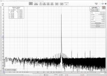
I noticed that I had mistakenly used too low VHREF voltages on the AK4490 board so the output was a tad low. Here is a new FFT spectrum with 2Vrms output. Now the THD+N is within datasheet limits.

AFAIK the artifacts around 1k are due to AK4118. Similar can be seen in jitter diagrams (as in Topping D70).
There seems to be lot of confusion about AK4118 even on ASR forum. Contrary to what some are stating AK4118 does not use the crystal or clock for reclocking the input. The crystal is only used for detecting the input sampling rate or for spdif output. Actually no crystal is required since AK4118 uses the PLL to retrieve the master clock. The measurements I have shown have been made with boards that have no clocks.
So even though AK4118 is claimed to be a low jitter spdif receiver there are better ones available (that actually do reclocking). E.g. ES9068AS as in Gustard x16 (see here). However even in AK4118 the jitter should be below audible levels.
Attachments
Last edited:
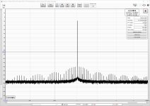
To wrap-up my monologue here are some jitter measurements.
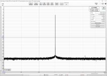
1. SPDIF (Coax) - AK4118 - AK4490

There are strange artifacts about 85Hz apart. These are the same artifacts as shown in previous post. I assume these are somehow related to AK4118 PLL.
Now let's add AK4137 into the stream.
2. SPDIF (Coax) - AK4118 - AK4137 - AK4490

This looks much better. The reclocking done by AK4137 seems to remove most artifacts. So SPDIF jitter is not that bad after all 😀
BTW the on board master clock that AK4137 uses is NZ2520SDA (24.576MHz). The clock enthusiasts probably regard it as "mediocre at best". But for us mere mortals with wax filled instead of golden ears it will do.
1. SPDIF (Coax) - AK4118 - AK4490
There are strange artifacts about 85Hz apart. These are the same artifacts as shown in previous post. I assume these are somehow related to AK4118 PLL.
Now let's add AK4137 into the stream.
2. SPDIF (Coax) - AK4118 - AK4137 - AK4490
This looks much better. The reclocking done by AK4137 seems to remove most artifacts. So SPDIF jitter is not that bad after all 😀
BTW the on board master clock that AK4137 uses is NZ2520SDA (24.576MHz). The clock enthusiasts probably regard it as "mediocre at best". But for us mere mortals with wax filled instead of golden ears it will do.
Attachments
Very nice work! Do you plan to release schematics and board design files?
Thanks for the compliments.
I'm doing this just as a hobby so I was not planning on selling these. There are also other issues that keep me from publishing the gerbers:
- Small size makes these very difficult for hand soldering. I would not dream on venturing into that. I have a reflow oven (albeit a cheap chinese) and I rarely hand solder SMDs.
- I use serial control (i.e. external MCU+SW) on all these AKM chips so you would either have to code your own SW or I would have to also give out the SW. The latter would quickly lead to bug fixing, releases etc. I have no time for that.
Also keep in mind that AKM chips are nowadays hard to come by since the factory fire. Only AK4490 is available at Digikey.
But anyhow here are the schematics for the AK4118+AK4137 board, AK4490 board and the XLR shield. As you will find out they are more or less according to datasheets.
Attachments
Now let's add AK4137 into the stream.
2. SPDIF (Coax) - AK4118 - AK4137 - AK4490
This looks much better. The reclocking done by AK4137 seems to remove most artifacts. So SPDIF jitter is not that bad after all 😀
Does a DAC like the ES9038Q2M need reclocking?
What can be used as a substitute for AK4137 if it is not available?
Most ESS dacs have an inbuilt ASRC. I don't know if it is better or worse than AK4137. However technically there should not be any need for AK4137 with ESS dacs.
I like that little AK4490 board. It would be nice to have one like that for the ES9038Q2M.
Do you think the TPS7A2033PDBVR is suitable? Or is LT3042 critical?
I guess I am dreaming of a little ES9038Q2M board with several TPS7A2033PDBVR and LM4562.
Why choose MELF resistors? Are they better than say 1206 metal film?
Do you think the TPS7A2033PDBVR is suitable? Or is LT3042 critical?
I guess I am dreaming of a little ES9038Q2M board with several TPS7A2033PDBVR and LM4562.
Why choose MELF resistors? Are they better than say 1206 metal film?
I'm using LT3042 only for VREF on AK4490 (and DVDD on AK4118 & AK4137). Other supplies use NCP703 which being an older chip is slightly worse than TPS7A2033 noise-wise.
For ES9038Q2M I would recommend similar approach as starting point. LT3042 on AVCC, TPS7A2033 on others. You can then later upgrade to discrete regulators for AVCC if needed. Since you already have an ES9038 board you would need some add-on boards for the new regulators. I would use MSOP and SOT-23 packages as they are relatively easy to solder by hand.
I guess thin film 1206 resistors would also work fine. I'm just used to MELF resistors. And actually they are interchangeable with the PCB package I use in my layouts (even 0805 resistors can be used).
So you are using only one LM4562 in the output and getting such amazing numbers?
Or are you measured balanced? (Into the sound card/interface?)
Is such a simple output filter (one LM4562) applicable or not applicable for the ES9038Q2M? Is it not applicable because current output is needed for ES9038Q2M to get such good performance?
Or are you measured balanced? (Into the sound card/interface?)
Is such a simple output filter (one LM4562) applicable or not applicable for the ES9038Q2M? Is it not applicable because current output is needed for ES9038Q2M to get such good performance?
The measurements were made with single-ended output (only one LM4562). And without any chassis or shield.
I think you already have a similar voltage-output stage on your ES9038 board.
I think you already have a similar voltage-output stage on your ES9038 board.
Right, so not applicable because current output I/V & filter is needed for ES9038Q2M to get such good performance? Correct?
I think you already have a similar voltage-output stage on your ES9038 board.
Yes, and I am already using LM4562. I am more probing at whether that is degrading performance in my case because ES9038Q2M needs I/V and filter? The correct answer is yes I assume? [But right now I am dealing with stuff before the output section.]
The datasheet does not specify the performance of voltage output but I have read somewhere that current output may have upto 12db lower THD.
Regarding AK4137, production was affected by the AKM plant fire. Individual AK4137 chips are no longer available. There may still be some in stock that are used to make Chinese AK4137 boards.
There is also a project to use 2 of AK4137 for upsampling and conversion of PCM to DSD256. IME that can make ESS dacs sound 'better.' Ending up using a similar idea for an ES9038Q2M dac project because people preferred the sound of it.
Simple DSD SRC for BeagleBone
There is also a project to use 2 of AK4137 for upsampling and conversion of PCM to DSD256. IME that can make ESS dacs sound 'better.' Ending up using a similar idea for an ES9038Q2M dac project because people preferred the sound of it.
Simple DSD SRC for BeagleBone
To wrap-up my monologue here are some jitter measurements.
1. SPDIF (Coax) - AK4118 - AK4490
There are strange artifacts about 85Hz apart. These are the same artifacts as shown in previous post. I assume these are somehow related to AK4118 PLL.
Can you explain in detail how to perform such jitter measurements?
Jitter test, etc.: http://www.collinsaudio.com/Prosound_Workshop/Julian Dunn_Jitter.pdf
J-test is for deterministic jitter (i.e. can be seen as spurs on an fft), not for close-in phase noise.
The original paper: http://s3t.it/data/uploads/docs/dig...and-assessment-in-digital-audio-equipment.pdf
J-test is for deterministic jitter (i.e. can be seen as spurs on an fft), not for close-in phase noise.
The original paper: http://s3t.it/data/uploads/docs/dig...and-assessment-in-digital-audio-equipment.pdf
Last edited:
- Home
- Source & Line
- Digital Line Level
- Modular AK4490 DAC