Not found it yet -say one thing for DIY Audio nearly always gets a line in most webpages I click on including the post above.
What I am getting is competition for sales of Magnum guns in the USA --as many have found out in the UK --order one up and at 2 am your door will burst open with heavily armed UK special police ---and then straight to jail .
What I am getting is competition for sales of Magnum guns in the USA --as many have found out in the UK --order one up and at 2 am your door will burst open with heavily armed UK special police ---and then straight to jail .

Thanks a lot, seems to be the correct one !...
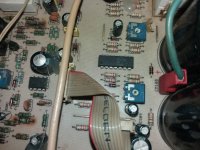
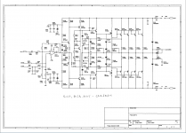
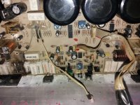
Due low resolution of image, I can not see Q401, Q402 - MJE ...
If somehow you have the secondary page in better res I'll be grateful if you'll forward to me.
As it is, anyway, will be a great help ! Thks again
Due low resolution of image, I can not see Q401, Q402 - MJE ...
If somehow you have the secondary page in better res I'll be grateful if you'll forward to me.
As it is, anyway, will be a great help ! Thks again
Last edited:
Hello !
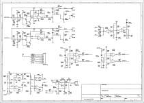
Thanks for diagrams 4 and 5 of 5. I need also the rest of diagrams (1,2,3 of 5) due I have a problem on input stage (not working anymore after disconnected both connectors). Servicing for input stage is difficult due no screws - only rivets !
Also I need power supplies diagrams due a lot of voltages on diagrams that different in reality.
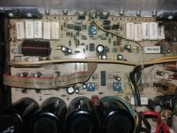
At this moment I have the ex-burned final stage working in only 2 transistors, but working - no idle current but some strange distorsions - green LED "signal" flashing on both channels altough only one has audio signal on it - (I've replaced on my working bench the 21V ac from big transformer with 18V ac only).
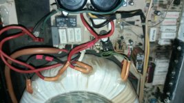
I don't know from wehere ± 15V , +28V etc - main trasformer has only 2x70V and 1x21V .
No distorsions if final stage powered by ± 15V , ± 25V but on ± 35V , ± 45V , ± 55V "clipping" strange and no more "clipping" furthermore till ±70V but still distorted.
Inputs directly on volume potentiometers due, as I said , input stage out of order after first disconnection (connectors were heavily covered all around by thermal glue and some force was needed to disconnect...). Or maybe not working on 18V....
Thanks in advance
Thanks for diagrams 4 and 5 of 5. I need also the rest of diagrams (1,2,3 of 5) due I have a problem on input stage (not working anymore after disconnected both connectors). Servicing for input stage is difficult due no screws - only rivets !
Also I need power supplies diagrams due a lot of voltages on diagrams that different in reality.
At this moment I have the ex-burned final stage working in only 2 transistors, but working - no idle current but some strange distorsions - green LED "signal" flashing on both channels altough only one has audio signal on it - (I've replaced on my working bench the 21V ac from big transformer with 18V ac only).
I don't know from wehere ± 15V , +28V etc - main trasformer has only 2x70V and 1x21V .
No distorsions if final stage powered by ± 15V , ± 25V but on ± 35V , ± 45V , ± 55V "clipping" strange and no more "clipping" furthermore till ±70V but still distorted.
Inputs directly on volume potentiometers due, as I said , input stage out of order after first disconnection (connectors were heavily covered all around by thermal glue and some force was needed to disconnect...). Or maybe not working on 18V....
Thanks in advance
Attachments
I'm sorry, there are no other parts of the scheme.
However, 20 years have passed since the production ...
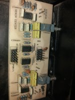
Check the Zenner Diodes for the +/- 15V voltage, the switches on the input module and the supply voltage of the output relay.
However, 20 years have passed since the production ...
Check the Zenner Diodes for the +/- 15V voltage, the switches on the input module and the supply voltage of the output relay.
input stage NOT out of order after first disconnection, just not powered correctly on my bench - they are working connected to main transformer as on factory
still I have some crossover distorsions on left channel ...
still I have some crossover distorsions on left channel ...
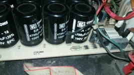
Add coils on the toroidal 20 turns with 0.8 mm insulated wire, in series with the primary, but reverse phased .
In this way, the secondary voltage is low, after rectification and filtration will reach +/- 75 V, enough for today's SOA transistors ...
In this way, the secondary voltage is low, after rectification and filtration will reach +/- 75 V, enough for today's SOA transistors ...
It is a good idea, but I think 20 turns reversed it is not enough to decrease the voltage by 25 percent ...
- Home
- Amplifiers
- Solid State
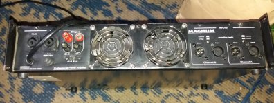
- diagram for Magnum-sa12 professional amplifier - SENIA Music echiv 1200 MachAudio