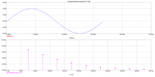
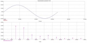
Frequency response
Attachments
Last edited:
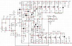
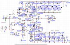
Class B, the operation of an amplifier with a very low quiescent current. 5-6par medium-voltage transistors for a load of 8 ohms is enough.what is mode B ?
2SC5171 is not for output, SOA DC30V@0.3A, DC50V@0.1A
7 pairs of transistors 1930/5171
Attachments
Last edited:
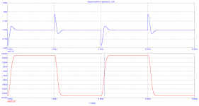
My Class-B amp (rated 150W/4R, 3mA idle current per output pair), simulated 100W/4R.
What do you say, is it good enough ?
(H2 160dB below fundamental)
What do you say, is it good enough ?
(H2 160dB below fundamental)
Attachments
Last edited:
How do you maintain 1ma bias on each output with thermal variation.
I still wonder what these 10 ohms in series with the input opamp supply are for, particularly the negative is decoupled by 1nF but not the positive.
Why both opamps are not AD825?
I still wonder what these 10 ohms in series with the input opamp supply are for, particularly the negative is decoupled by 1nF but not the positive.
Why both opamps are not AD825?
My Class-B amp (rated 150W/4R, 3mA idle current per output pair), simulated 100W/4R.
What do you say, is it good enough ?
(H2 160dB below fundamental)
At 1 kHz, in almost any circuit, the distortion is small.it is better to look at 20khz .In addition, in Class B at a low signal level.
The quiescent current is maintained by local feedback in the output stage of the op-amp. There is no thermal stabilization.At low quiescent current, self-heating of transistors does not occur.I forgot to draw the 1NF capacitor .When modeling it is necessary to use full opamp modelsHow do you maintain 1ma bias on each output with thermal variation.
I still wonder what these 10 ohms in series with the input opamp supply are for, particularly the negative is decoupled by 1nF but not the positive.
Why both opamps are not AD825?
What are the good thd numbers ? -120dB at 20kHz ?
and these numbers ?
THD 0.1W/4R
1k -190dB
10k -137dB
20k -117dB
THD 1W/4R
1k -180dB
10k -137dB
20k -120dB
THD 10W/4R
1k -170dB
10k -136dB
20k -120dB
THD 100W/4R
1k -160dB
10k -134dB
20k -119dB
and these numbers ?
THD 0.1W/4R
1k -190dB
10k -137dB
20k -117dB
THD 1W/4R
1k -180dB
10k -137dB
20k -120dB
THD 10W/4R
1k -170dB
10k -136dB
20k -120dB
THD 100W/4R
1k -160dB
10k -134dB
20k -119dB
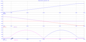
It is difficult to compare data from different simulators. Besides not knowing your scheme.Better tell us about the distortion on a small signal, where the influence of a small quiescent current is more noticeable.
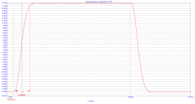
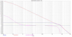
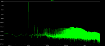
Graph of the distortion at low power . The quiescent current is 0.4 Ma per pair
Graph of the distortion at low power . The quiescent current is 0.4 Ma per pair
Attachments
All these simulated numbers (mine included) are bedtime stories. Impossible to achieve them in the real circuit. What's the point? To show the simulator capability ?
Now it's fairy tales. 100db of loop gain at 20kHz ,of which 70db in the OOOS loop are not lying on the road. and it's not going anywhere.All these simulated numbers (mine included) are bedtime stories. Impossible to achieve them in the real circuit. What's the point? To show the simulator capability ?
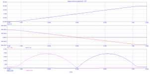
Continue. The scheme is based on the scheme from the old Soviet magazine "Radio" No. 1 for the distant 1989 year.The accumulated experience allowed it to be upgraded by eliminating the causes of possible malfunctions.The scheme can work in two classes AB+B and pure class B. The MS-12 graphs show the modes of active elements and the dependence and spectrum of Kg distortions at different power levels.So so on this forum it is customary to remove distortion at a frequency of 1 kHz ,then all measurements are made at this frequency.
In the distortion measurement archive.
In the distortion measurement archive.
Attachments


- Home
- Amplifiers
- Solid State
- The power amplifier in the mode B.