I know, yet one more soft start 🙂
But here it is, I'm sharing what I have, which may be of interest to some users.
It's only the soft start function, for one toroid only, and it's activated by a push button with a led to show status.
Nothing more beyond that. No dc blocker, no snubbers on the mains, except the one on the triac, no ground lifter or anything else of that nature.
But also no electromechanical relay, no power dissipating stuff like power resistors, no MOVs, nothing bulky.
Just an 8 pins PIC to handle it all, by phase control, like a plain old dimmer.
The unit is in standby when power is first applied, waiting for the push button to be hit. When the button is hit, the start up sequence starts, the led blinks during the whole process, while the push button is ignored.
Once the full sequence is done, the led and toroid are fully turned on and the push button is polled again, with a small delay, waiting for the next push to shut the unit down and go back to stand by. The led is turned off as well as the toroid at that point and so the status is back to the same as when power was first applied.
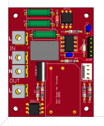
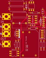
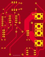
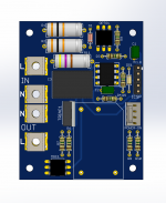
The pcb is 55x70mm. The PIC can be reprogrammed on board via the ICSP header and a pickit or whatever is used to do pic programming.
I will post more stuff in a while. The gerbers, pic asm source code..
I have already verified the software using a breadboarded version of the circuit on a 200VA toroid, and it worked just fine. I didn't have a bigger toroid handy, so I don't know how it will behave on that, but the software is easily adjustable in case of need for a hard to handle load.
I have pcbs coming to me, so I'll be testing the whole thing built for real in a few days.
Maybe this might be of help to some users, so I'm sharing it.
The start up sequence is smooth, starting with pulsing the triac gate (~250us) at ~9us from zero-crossing, for several cycles, then the delay decreases by ~500us at each step in the sequence, all the way down to zero delay when the sequence is all done and the triac is then fully turned on permanently (well, at least until we tell it to shut down, or power is lost).
The zero-crossing is sensed via optocoupler, as well as the triac triggered via optotriac.
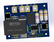
I used a 5V power module instead of a transformer based PSU for the pic power, so fewer parts and smaller footprint overall, plus it turns out a bit cheaper as well, not to mention simpler to assemble.
I priced all the parts from mouser and compiled a excel based BOM, which should make it easier for anyone to make. It's fairly cheap to make, with less than 15euros worth in parts, plus the pcb.
But here it is, I'm sharing what I have, which may be of interest to some users.
It's only the soft start function, for one toroid only, and it's activated by a push button with a led to show status.
Nothing more beyond that. No dc blocker, no snubbers on the mains, except the one on the triac, no ground lifter or anything else of that nature.
But also no electromechanical relay, no power dissipating stuff like power resistors, no MOVs, nothing bulky.
Just an 8 pins PIC to handle it all, by phase control, like a plain old dimmer.
The unit is in standby when power is first applied, waiting for the push button to be hit. When the button is hit, the start up sequence starts, the led blinks during the whole process, while the push button is ignored.
Once the full sequence is done, the led and toroid are fully turned on and the push button is polled again, with a small delay, waiting for the next push to shut the unit down and go back to stand by. The led is turned off as well as the toroid at that point and so the status is back to the same as when power was first applied.
The pcb is 55x70mm. The PIC can be reprogrammed on board via the ICSP header and a pickit or whatever is used to do pic programming.
I will post more stuff in a while. The gerbers, pic asm source code..
I have already verified the software using a breadboarded version of the circuit on a 200VA toroid, and it worked just fine. I didn't have a bigger toroid handy, so I don't know how it will behave on that, but the software is easily adjustable in case of need for a hard to handle load.
I have pcbs coming to me, so I'll be testing the whole thing built for real in a few days.
Maybe this might be of help to some users, so I'm sharing it.
The start up sequence is smooth, starting with pulsing the triac gate (~250us) at ~9us from zero-crossing, for several cycles, then the delay decreases by ~500us at each step in the sequence, all the way down to zero delay when the sequence is all done and the triac is then fully turned on permanently (well, at least until we tell it to shut down, or power is lost).
The zero-crossing is sensed via optocoupler, as well as the triac triggered via optotriac.
I used a 5V power module instead of a transformer based PSU for the pic power, so fewer parts and smaller footprint overall, plus it turns out a bit cheaper as well, not to mention simpler to assemble.
I priced all the parts from mouser and compiled a excel based BOM, which should make it easier for anyone to make. It's fairly cheap to make, with less than 15euros worth in parts, plus the pcb.
Attachments
-
 Screen Shot 2020-12-24 at 7.46.17 PM.png314 KB · Views: 595
 -
 eagleUp_PIC12F629 soft start_board_top.jpg409.3 KB · Views: 596
 -
 eagleUp_PIC12F629 soft start_board_bottom.jpg260.4 KB · Views: 582
 -
PIC12F629 soft start sch.pdf26.1 KB · Views: 287
-
PIC12F629 soft start dims.pdf20.8 KB · Views: 158
-
PIC12F629 soft start placement.pdf19.7 KB · Views: 168
Ok, here is the rest of it.
I had to zip up the source code file and the excel BOM.
The gerbers are those I used lately to order the pcbs, which are already made and shipped out to me. I'm awaiting reception in a few days. And I will build and test it again.
The source code is PIC assembly, not C or whatever... Done with MPLabX, and I used a pickit3 to program my chips to test on breadboard.
Others have done similar builds (hello Nigel 🙂🙂🙂).
I'm a first timer at PICs, and it's, almost, my first PIC assembly program, as I already did one before this one that was aimed at 2 toroids plus a few other features.. I also did one other program to do housekeeping for a headamp.
As a first timer, I heavily document my asm source code, so I can go back much later and know more or less what I did without doing too much head scratching. This should also be good for other noobs like me to learn some more and get into it.
It was a nice exercise, but it should be useful.
Although a few odds and ends should be added to it for a more full blown build, like a dc blocker at least, to limit the toroid hum..
So, there it is then..
Attachments
Nice idea. I looked at your zero-xing detector, as I also needed one in my high-voltage delay unit.
I found I could get a good signal with just a 1Meg resistor into a 4.7V zener to ground.
It probably wouldn't work in your case as your circuit is isolated from the mains; mine is working from the secondary and is referenced to ground.
I did use the exact same PIC that you used ;-)
Jan
I found I could get a good signal with just a 1Meg resistor into a 4.7V zener to ground.
It probably wouldn't work in your case as your circuit is isolated from the mains; mine is working from the secondary and is referenced to ground.
I did use the exact same PIC that you used ;-)
Jan
Last edited:
Cool! 🙂 Thanks Jan.
The main thing with that optocoupler is to give it enough current passing through that led, or it will have trouble "seeing" anything...
I hope they don't obsolete that chip too soon, again. It's hard to keep up with them, always obsoleting everything too fast, so not only we can no longer find the parts, but once we get used to something, we're already behind the times...
Anyway, for this simple one I used the 12f629, but for the dual toroid I used a 16f688 (yes, already considered obsolete!! Geez!!)
Thank you for doing this post, really..
That's a project I am working on too, are doing it this way? I am triggering Triac on +ve halh waves, do you have a snapshot that shows how waves switching progress? I am showing different triggering timings, look at them in backwards order, so the concept is the same for all of them, just different angles till fully switched ON. Which one are you doing anyway?
That's a project I am working on too, are doing it this way? I am triggering Triac on +ve halh waves, do you have a snapshot that shows how waves switching progress? I am showing different triggering timings, look at them in backwards order, so the concept is the same for all of them, just different angles till fully switched ON. Which one are you doing anyway?
Attachments
Last edited:
are doing it this way? I am triggering Triac on +ve halh waves, do you have a snapshot that shows how waves switching progress? I amshowing different triggering timings, so the concept is the same for all of them, just different angles. Which one are you doing anyway?
I'm not sure what I'm looking at there. If some more info was given about what each trace is, maybe I could respond better.
But basically, it makes no difference which half wave it is, wether positive or negative, it's exactly the same.
The zero crossing sensor causes edges to happen on all of the crossings, whichever way the wave is going, up or down.
What I do is use those zero cross edges to trigger interrupts, and then apply a delay from that to trigger the triac with a ~250us pulse.
One thing to watch out for, is to not trigger the triac too close to the next zero crossing, or it might stick (stay on). The datasheets mention to at least leave about 200us before the next crossing, to make sure.
So, the zero cross sensor gives edges, which we use as a reference to delay from. The edge trigger an interrupt, although it won't be exactly "on" zero crossing, because the circuitry has a small reaction time, plus the pic needs a few us to treat the interrupts, but no matter, a few us aren't much compared to the ms of half waves.
So what I did was to delay initially the triac trigger pulse about 9ms from the detected zero crossing, give it a ~250us pulse, which is sufficient to have the triac "stick" (stay on), but it will only stay on until the next zero crossing, and the next half wave, wether negative or positive, is then treated exactly the same. Triacs don't care about polarity.
So we're never looking at full waves, being 20ms long with a 50hz mains. Instead we're only considering all the half waves, the same, of 10ms.
Since the reaction isn't instantaneous, the 9ms delay we apply won't be exactly that from the zero crossing, but no big deal, because we give the triac its 250us pulse, which makes it stick, and there is much more than 200us left before the next crossing..
Do a few half wave the same way, then go on to the next step in the sequence, taking out 500us from the delay, and repeat that, until we have no left over delay to apply, so the triac is triggered for a full half wave each time, so then we can turn it on permanently and leave it that way, until further notice.
Some have different methods of doing this. Some don't use interrupts. Some prefer steps of 1ms between each section in the sequence. But I did it this way because it's smoother.
We can easily adjust 2 parameters in the software to decide how many half waves are done the same in each step in the sequence, and then how many sequences we make, if we vary the delay a bit. But tweaking the first parameter should suffice.
I tried making an illustration showing all the steps, but this takes time and I was trying to use illustrator for this, which is cumbersome to use, not fast at all.
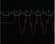
Ok, I see it mostly about right, although something odd may be going on.
If I get this right, that yellow trace would be the zero cross signal.
The blue one the triac's trigger.
And the red one the load's.
What do you use to do this?
It's not in sync to stay stable, so it's a bit hard to see everything, with it moving all the time. Maybe if possible, put a sync on the yellow trace, so it won't move all over the place..
Is this sim done from my software?
In the mean time, I'm adding one more better visual, although not yet with the power module...
Attachments
Last edited:
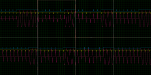
Sorry, I deleted previous post to make things clearer for you. Trace colors are as you have already mentioned:
Blue: Triac trigger signal
Yello: ZCD
Red: Signal across the transformer
You can download the GIF images and look at the actual frames.
Your ZCD approach is prone to noise, so you will have issues later on real HW assembly.
I simulated your code, result is below, honestly it is a real mess, please be patient and look at it carefully:

I am following TSR method, I am only working on either +ve or -ve half waves:

Anyway, did you test your work to see what the correct angles are, because according to TSR, the delay to avoid inrush current differs from one transformer to another.
Blue: Triac trigger signal
Yello: ZCD
Red: Signal across the transformer
You can download the GIF images and look at the actual frames.
Your ZCD approach is prone to noise, so you will have issues later on real HW assembly.
I simulated your code, result is below, honestly it is a real mess, please be patient and look at it carefully:
I am following TSR method, I am only working on either +ve or -ve half waves:
Anyway, did you test your work to see what the correct angles are, because according to TSR, the delay to avoid inrush current differs from one transformer to another.
Last edited:
Ok, something isn't quite right. Mostly, but not quite. Some small bit doesn't look right and there is nothing in the code to do such a thing.
The software uses the zcd as the starting point, from which is applies a delay before it gives the triac the trigger pulse.
But that red trace is showing something that shouldn't be there, right at the beginning of the half waves. That small spike shouldn't be there, only the larger one that grows over the sequence at the end of the half wave, not the beginning.
There is nothing in the software to send a trigger pulse at the beginning of each half wave. So something is odd here.
But still, even if it did this, it would work to limit the inrush current.
And my test showed me that it was doing the sequence just fine with the intensity larger at each step, so the toroid was being powered progressively.
Now of course each transformer will have its own behavior, as they're not quite all the same, but applying that basic scheme should work as is on any toroid, or any transformer, and even on lamps or whatever else.
I tried it on light bulbs first, and they lit up gradually, properly, as expected.
Not sign of that extra tiny spike at the beginning of each half wave. I don't know what's going on with those sims, but something isn't entirely right.
ignore the tiny spikes, you will not see them on real oscilloscopes as I have not optimized the sim, anyway, the sim is correct and shows what your schematic and code are doing. When you see a sine wave at the beginning, then it is there.
Look at the attached file for ZCD and Inrush current limiting, these are a good read. Actually, you need to understand how transformer demagnetization works, your test using a bulb can't reflect actual transformer behavior nor the fact your project is successful.. Also dimming techniques used with bulbs differ from those used for motors/transformers.
Look at the attached file for ZCD and Inrush current limiting, these are a good read. Actually, you need to understand how transformer demagnetization works, your test using a bulb can't reflect actual transformer behavior nor the fact your project is successful.. Also dimming techniques used with bulbs differ from those used for motors/transformers.
Attachments
Last edited:
I did a similar circuit a couple of years back.
I omitted the push button circuit and made the power up sequence automatic.
It also dealt with power downs and brown outs by monitoring the mains.
Power to PIC was by a resistor dropper off the mains.
Worked very well.
I omitted the push button circuit and made the power up sequence automatic.
It also dealt with power downs and brown outs by monitoring the mains.
Power to PIC was by a resistor dropper off the mains.
Worked very well.
Ok, something isn't quite right.
But that red trace is showing something that shouldn't be there, right at the beginning of the half waves. That small spike shouldn't be there, only the larger one that grows over the sequence at the end of the half wave, not the beginning.
I suspect that spike is caused by the transformer inductance shifting voltage and current out of phase. The triac will only switch off at zero current and that point is delayed by the transformer inductance.
Hi nigel 🙂
you may have a point there, that could explain what the deal is with that tiny spike early in the half waves.
So that would have nothing to do with the software triggering something early on, but just rather a slight delay from the triac when it shuts off a tiny bit beyond the next crossing.
I suppose this is no big deal and it works anyway.
When the start up sequence starts, the delay is about 9ms, so that's about 90% of the half wave away from the crossing starting it. This leaves a little less than 1ms, due to reaction times, to issue the 250us trigger pulse and still be more than 200us away from the next crossing. This satisfies the requirement stated in the triac's datasheet, so the triac shouldn't be subject to not being able to disengage at the next crossing, so it wouldn't stay on.
When the delay backs down to 4.5ms from the crossing, we're at 50% of the half wave, so that's a 90degrees shift, the maximum in the half wave.
It's true the test on light bulbs isn't anything like a real toroid, but at the time, I had no toroid on hand to test with, so that's all I had, and those bulbs are also small and low power, like 20W or whatever.. I knew it wasn't the best test, but at least it tested the software's sequence, which revealed the dimming effect, quite visible with the light bulbs. And it all works as intended.
Once I borrowed a real toroid, I tried it with a quick mockup bridge and cap banks (30000uF) to have a psu similar to the run of the mill power amp, so the load was a complex type just like what needs to be handled.
And as far as I can see, it all works just fine.
One thing that might happen though, depending on the toroid and how well they prevent vibrations, is there may be a little bit of a hum for a short time, during the sequence, until it's fully turned on, which lasts some 1.5sec or so. No big deal, it's unavoidable with the switching during the half waves with those sharp edges, and it stops once fully turned on.
I don't think there is any need to bother with any more advanced zero crossing sensor. I didn't want to feed the mains directly in the pic, so I used the method with the photocoupler, so there is galvanic isolation. I see no need to make the zcd any more complex. Works just fine.
At some point in the future, I should be able to get my hands on a bigger toroid, and I'll do more testing then, but I think it looks like it'll work just fine as it is now. If there was any reason to further lower the impact of inrush current for a particularly difficult load, it's easy to add more cycles in each of the steps in the start up sequence, which would lengthen the whole sequence a bit and smooth out some more..
I don't think there is much to worry about demagnetisation. And I don't see a point in having a reverse shut down sequence to gradually power down. I think this would only be more intellectual masturbation and a waste of time.
When we power down, we just shut of the triac, and that's it. It's not a relay, there are no contacts and no chance of arcing, and I don't see a need to mitigate any kind of out-rush....
There was one feature that I've been thinking about that could be of help to some:
Having one more input that would be used as a trigger in the same way as the power push button, so the start up sequence could be initiated either by the push button or that extra input.
This would allow daisy-chaining of the modules, so more than one toroid could be started up in a sequence, to avoid having more than one toroid starting up at once.
And there would be no limit to how many modules could be daisy chained, so 3 or 4, or more, could be handled.
Only one link would be needed between the soft start modules to daisy chain them.
Also perhaps adding a dc blocker could also be a nice thing. But then the pcb size grows... And feature creep comes in.. 😀😀
I found I needed a heat sink on the triac for higher power systems.
Mine would drive up to 2000 watts system.
Mine would drive up to 2000 watts system.
Years ago I developed a power sequencer, switching on audio sources first, then preamp, DAC, what have you, last power amp. Turn off in reverse order. Comprised a set of 5 soft start units similar to those described here.
One difference: I bridged the triac with a relay after a few cycles of full power, to avoid causing mains DC from the triac threshold. At switch off, first open the relay, then the triac.
Attached an example with a high power amp load.
Jan
One difference: I bridged the triac with a relay after a few cycles of full power, to avoid causing mains DC from the triac threshold. At switch off, first open the relay, then the triac.
Attached an example with a high power amp load.
Jan
Attachments
I found I needed a heat sink on the triac for higher power systems.
Mine would drive up to 2000 watts system.
Yes, that's one thing I was considering. At what point do we really need to add a heatsink.
I thought maybe it wouldn't be needed until we load maybe at least some 1kva or perhaps 1.2kva. But no sure. Maybe a good idea to allocate a bit more room around that triac in case a heatsink needs to be added...
You can work it out from voltage across triac (about 1.5 volts) when on times current through it.
This gives watts.
Then work out how hot you will want the triac to be and get a heatsink w/degrees C accordingly.
This gives watts.
Then work out how hot you will want the triac to be and get a heatsink w/degrees C accordingly.
You can work it out from voltage across triac (about 1.5 volts) when on times current through it.
That's the part I wasn't sure about. How much drop we get across it.
So then it's easy to figure out once this figure is known.
This gives watts.
Then work out how hot you will want the triac to be and get a heatsink w/degrees C accordingly.
That I can do, now knowing the voltage drop 🙂 I can even do it quickly via simulation..
- Home
- Amplifiers
- Power Supplies
- PIC based stand alone soft start