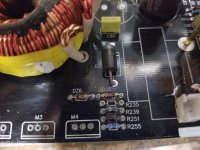
Working on an Audiopipe ACPLe-2004. Would anyone happen to know the value of R250 and R251 in the power supply?
The gate signal from the KA3525 Goes to R251 and R255. R255 is a 10K to ground. R251 feeds the gate signal to R235 and R239 22 ohm gate resistors to the power supply inverters. The same on the other side for R250. Maybe an educated guess based on the set up?


Were they completely burned open?
If not, what did they read?
Do the two series diodes connect between the drains of the FETs and the point where the two burned resistors connect to the gate resistors?
If not, what did they read?
Do the two series diodes connect between the drains of the FETs and the point where the two burned resistors connect to the gate resistors?
I think the original resistor may have been something near 27 ohms (especially since one read near that).
You can't go too low or the zener circuit can't function (will likely never actually do anything, anyway). If you go too high, the FETs will run hot due to poor gate drive.
Confirm that the FETs run cool at idle.
If you want to experiment, you could install higher value resistors in those locations to see where the FETs begin to run hot.
- Home
- General Interest
- Car Audio
- Audiopipe ACPLe-2004