I need a little help in trying to figure out how to correctly troubleshoot this amp. One side of the outputs (Leftside) are completely shorted. I pulled the P12PF06 and P14NF06 FET's. Amp still would not start. So I pulled the other side, the amp runs now. I have a neg and pos rail voltage of 25v.
I am using the MRD-M501 schematic, seems to be very close. I am not sure how to check for a input signal as well as a output signal on the IC501. Any help would be appreciated.
I am using the MRD-M501 schematic, seems to be very close. I am not sure how to check for a input signal as well as a output signal on the IC501. Any help would be appreciated.
If you drive a strong signal into the amp, do you see a drive signal reaching ANY of the output transistor gates?
Positive to negative 'what'?
You need to give the circuit board designations and the terminal that you're reading (I.E, Qxyz, gate) and the amplitude of the voltage. This is best done with a scope, giving the vertical amp and timebase settings. Photos of the waveforms are a bonus.
You need to give the circuit board designations and the terminal that you're reading (I.E, Qxyz, gate) and the amplitude of the voltage. This is best done with a scope, giving the vertical amp and timebase settings. Photos of the waveforms are a bonus.
Taking readings from Q506 gate.(P12PF06). I am getting this reading on all the gates of the P12PF06 FET's, both left and right. I am fixing to take the reading from the P14NF06, if you need it also?
Attachments

Last edited:
The driver IC appears to have survived but Checking in differential mode on DC coupling would be more definitive.
A differential input uses two inputs to produce a single waveform. The simplest way to get a differential input is to use a differential probe. A differential probe has two signal leads and a mixer amplifier built into it. It feeds the scope a normal signal (a composite of the two signals input into the differential probe). The problem with differential probes is that they're expensive. The cheapest ones are about $60 used and they can cost more than $3000.
The alternative is to use two scope probes and and both inputs of your oscilloscope. This is how you have to set up your scope:
Two probes
Both scope inputs used
Input set to add
Both channels set to DC coupling
Both vertical amps set to the same voltage
Ch2 input set to invert
Bandwidth limited (works best for most measurements in car amps)
Trace aligned to the reference line on the scope's display
Ground leads for both probes connected together
After setting up the scope, you need to confirm that it's working as it should. With the vertical amp set to 5v/div, touching the probe that's connected to Ch1 to the positive terminal of your 12v power supply should make the trace deflect about 2.5 divisions up from the reference (like it always does, seen below). Doing the same with the probe connected to Ch2 should make the trace deflect down about 2.5 divisions. Touching both probes to the positive terminal of the 12v power supply should cause no deflection. If it does, something isn't right.
I know that this may not be as simple as the isolated scope but if you take the time to learn it one time (even if it takes an hour or more of your time), you have that knowledge and this tool to use for the rest of the time you need to use a scope. Using the analog scope will give you much larger and cleaner waveforms.
So after I get the scope set up with both probes, CH1 and CH2 and I place the both probes on the 12v positive terminal, there should be no deflection? I am getting deflection, Ch1 up and Ch2 down. What have I missed?
I have a +/- button between the ch1 and ch2 switch. Is that the correct button. Its a math button? If not how would I add them both?
I am placing the probes at the same time, yes sir
I am placing the probes at the same time, yes sir
If you get 2 traces, it's not adding the channels. I don't know what the solution is for your scope. You may have to find it by trial and error.
This may sound funny, but I am getting 3 traces, ground ref, pos, and neg deflection of about 2.5 blocks
You may have to turn the two other traces off. The 'ground reference' is likely the trace you want.
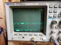
Repost the waveforms. This time. the inverted channel of the scope will be on the source pad. The normal channel will be on the gate pad.
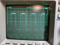
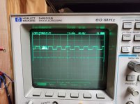
The neg signal is from Q506, inv probe to source and normal to gate. Checks the same on all of the P12PF06 pads.
The pos signal is from Q508, probes the same way. All checks on the P14NF06 pads are the same.
The pos signal is from Q508, probes the same way. All checks on the P14NF06 pads are the same.
Attachments
- Home
- General Interest
- Car Audio
- Alpine MRD-M500