I learned that there is a Vhk(max) rating which is typically at 150V, which means heater should not be more negative than cathode by 150V. It is therefore necessary for some circuit to have the heater elevated. But is there a max for heater to become above the cathode potential? How much would that typically be for typical preamp tubes?
Same magnitude either way, but it varies from 90VDC to 200VDC. Check the data sheets.
Don't even get close to the maximum in your circuit.
Frank's electron Tube Data sheets
Don't even get close to the maximum in your circuit.
Frank's electron Tube Data sheets
Last edited:
Usually the number for positive and negative voltage limits are the same. In some odd cases they will specify different numbers for positive and negative with respect to cathode.
Note that some tubes like 6sn7 and 12at7 have a limit like 90 volts while the 12ax7 may have 180.
Note that some tubes like 6sn7 and 12at7 have a limit like 90 volts while the 12ax7 may have 180.
For a 12AX7, the maximum cathode current is 8mA, the maximum plate dissipation is 1 Watt, and the filament to cathode is 180V maximum.
If the cathode only has to be capable of passing 8mA, then you can use a lot of insulation between the filament and the cathode, and still get the cathode hot enough for 8mA.
A 12AT7WA has a maximum 20mA cathode current, and maximum 100V filament to cathode, and a 2.5 Watt maximum plate dissipation.
Probably there is a lot less insulation from the filament to the cathode, to get the cathode hot enough to do 20mA.
Both tubes have the same filament voltage and current rating.
Just a theory of mine.
Last edited:
Not sure I'm seeing a link there ??
The WA series valves are afaik, just screened to confirm suitable operation at a higher limit level (eg. Vhk limit raised from 90V to 100V for a given leakage current). The WA screening for AT7 also confirms 2000 cycles with 135V and 7.5V heater operation for lifetime stress capability.
The WA series valves are afaik, just screened to confirm suitable operation at a higher limit level (eg. Vhk limit raised from 90V to 100V for a given leakage current). The WA screening for AT7 also confirms 2000 cycles with 135V and 7.5V heater operation for lifetime stress capability.
TV tubes have much higher Vhk voltage but heater power and cathode current is the same , so it's all about the thicknes of alumina insulation . Of course they wanted to use as little as possible 😀 , simple economy
The thickness and heat conductivity of the insulator doesn't matter if the heat transfer is by radiation not conduction
The thickness and heat conductivity of the insulator doesn't matter if the heat transfer is by radiation not conduction
Last edited:
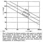
Try finding Rodenhuis, Santing and Van Tol, "The life and reliability of valves", Philips Technical Review, vol. 18 (1956-1957), number 7, pages 181...216, December 1956. It is freely accessible somewhere on the Internet.
On page 188 it is explained that when the heater is positive with respect to the cathode, at spots where the alumina touches the cathode tube, too high voltages lead to electrolysis of the alumina insulation, which releases oxygen, which oxidizes the tungsten, which leads to a path of conductive tungsten oxide through the alumina insulation. When the heater is negative with respect to the cathode, you get a similar reaction, but with the nickel of the cathode tube oxidizing. This latter reaction is slower, which is why valves often have a lower voltage rating with the heater positive than with the heater negative with respect to the cathode.
On page 188 it is explained that when the heater is positive with respect to the cathode, at spots where the alumina touches the cathode tube, too high voltages lead to electrolysis of the alumina insulation, which releases oxygen, which oxidizes the tungsten, which leads to a path of conductive tungsten oxide through the alumina insulation. When the heater is negative with respect to the cathode, you get a similar reaction, but with the nickel of the cathode tube oxidizing. This latter reaction is slower, which is why valves often have a lower voltage rating with the heater positive than with the heater negative with respect to the cathode.
Attachments
Last edited:
Januaryabc, you don't mention the valve types that you are interested in, or have inspected datasheets for, and from which you make an observation of Vhk-max = 150V ? 150V or higher would indicate you have inspected valve datasheets for audio output stage valves ?
Were there some typical preamp valves that you haven't seen a datasheet showing a Vhk-max rating?
Note that the Philips Tech Review article is summarising sudden h-k short-circuit type failure, where the failure rate of a population of valves increases with operation at higher and higher Vh-k. There is a separate hum related effect where increasing hum can occur due to h-k leakage, and that can mean a valve is deemed to have failed, or can be the reason to elevate the heater so as to supress hum leakage current.
For a 12AX7, ... A 12AT7...
I'm about 99% sure a lot of these cathode assemblies are the same. The difference may be marketing and specs.
Very early on, 12AX7 was used in op-amps where V2 could have large cathode swings (and of course all heaters were on one circuit).
12AT7 is almost certainly the same stuff BUT it is a TV Tuner tube. Even in cascode it is unlikely to have the heater over 90V. So that's all they promise us.
The heater insulating rating is probabilistic. Many samples of a type will stand much more than rating. (It is hard to make insulation that won't stand 300V.) But some small fraction have flaws which stand 90V, 150V, but not 300V. Since this is rarely a critical spec, and tube makers want to sell all they make, they don't promise more than we demand(ed).
When you look at post #7, you will see it's a lifetime issue rather than an immediate breakdown issue. The example in the graph can stand 100 V for 10 000 hours at nominal heater temperature or 1000 V for 20 hours at nominal heater temperature, both for 1 % probability of failure.
At some point in time, with excess filament to cathode voltage, the filament to cathode interface begins to break down, as described in an earlier post in this thread.
Then you can take a simple Ohmmeter and read the leakage resistance even when the tube is out of the socket, and is cold.
I had that happen on the triode sections of some 7199 tubes that were used as concertina phase splitters.
The leakage resistance of the filament to cathode causes unequal gains of the cathode and plate outputs of the concertina, because the leakage resistance is in parallel with the cathode resistor of the concertina.
And, that leakage resistance can also pass some of the AC filament voltage onto the cathode, and effectively from there to the later stages. It does not have to be a concertina, it can be a simple common cathode gain stage that does not have a bypass cap across the cathode self bias resistor.
The post #7 graph is 'for guidance only' (and of the probability trend of a large population - rather than viewing it on a single example basis), as it is based on extrapolation from accelerated testing, and is related to the oxidation and electrolysis mechanism that ends up as a h-k short circuit.
The Philips paper unfortunately does not have data on what happens prior to a particular valve suddenly exhibiting a h-k short circuit, as the test setup only had a sense circuit to indicate when a 'short circuit' occurred. I would anticipate that Rh-k would have reduced over time, but it is uncertain how that would characterise itself given that alumina impurities is the other well known mechanism for Rh-k degradation.
For a concertina, if the top and bottom resistances were a fairly high 100kohm, then a 10Megohm Rh-k to 0V would change the bottom resistance by 1% - which would cause an insignificant change to the gain of each side. Given the heater would be typically negative relative to the cathode in a cathodyne, then if the 7199 was showing failures it could be from a short-circuit mechanism as per the Philips Tech Review, although that h-k polarity has a 10x longer expected service life.
The 12AT7WA has a 500hr test pass rating of >50Megohm, along with an initial >100Megohm requirement. I didn't measure below 100Megohm in a batch of 10 vintage 12AX7 of unknown origin.
Last edited:
One of the 7199 tubes was 100k Ohms. That is significant enough for a lot of effect.
The amplifier worked, but the un-balanced output from the concertina added 2nd harmonic distortion (and 2nd order intermodulation distortion).
Just something from my experiences.
The amplifier worked, but the un-balanced output from the concertina added 2nd harmonic distortion (and 2nd order intermodulation distortion).
Just something from my experiences.
Do you recall if you measured or calculated the "100k Ohms" with a typical DMM, or at the 100Vdc datasheet limit, or at the operating circuit conditions (eg. perhaps a Vdc lower than 100V) ?
Just a DMM with its low voltage Ohmmeter was all that was needed to read 100k.
Good tubes read 'overload' (out of the 40 Meg Ohm range of the ohmmeter).
No need to explain further, is there?
Good tubes read 'overload' (out of the 40 Meg Ohm range of the ohmmeter).
No need to explain further, is there?
Thanks for clarifying. The subtlety is that the measured resistance could vary with applied voltage and polarity, depending on the mechanism that is causing the low resistance. I just haven't had a 'bad' valve to check for that.
So you have a DC voltage, where there's a signal going through the tube the AC peaks could push beyond the Vhk limit?
Also should you biasing the heater against the cathode, as the tube operates the filament tracks the AC signal?
I take it the easy option is just make sure your voltage limits all sit within the specifications.. then you don't have to play silly-bs.
It doesn't seem a problem when tubes like the 6AS7 support 300V Vhk. It looks like you have a reasonable cushion outside of the operating 250V Va max.
- Home
- Amplifiers
- Tubes / Valves
- Vhk(max) rating