So I was planning on posting a whole set of - how I built my SE II and got all lazy but thought folks might find this useful.
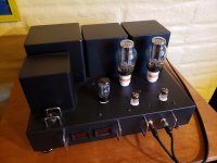
I had trouble with Hammond 276 and 376X power transformers running REALLY hot so ended up going to a B373EX which is HUGE, but runs really cool. Used Edcors for outputs and mil-spec Vishay-Dale resistors (Mouser) or matched ones from Sonicraft.
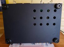
All of the resistors are mounted on the top and caps on bottom. Board is mounted with 1/2" long standoffs to give clearance for the resistors and put the tube sockets about flush. All the board mount and transformer mount screws are 10-32 button head screws.
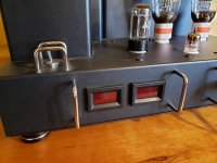
Super oversized heat sinks on the mosfets and power IC which resulted in this chassis arrangement with digital current meters for bias monitoring.
So what you get are some pictures but also PDF's that if you print full size will give you the hole layouts for everything. I tried to make notes on the PDF's but if you have questions, post them.
The transformer covers are from Ebay and work great. The small handles over the switch and front and back are there to protect connectors and frankly, aesthetics.
I used Greenlee chassis punches for the tube and switch holes as well as a bunch of vent holes in bottom cover.
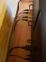
The front RCA inputs are probably not ideal visually but keeps cable runs to absolute minimum.
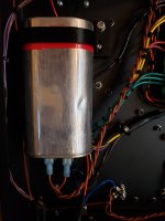
I have large motor run cap set in the underside of chassis in a 3D printed clamp.
There are four extra holes in the top to expose the four adjustable pots and I cover them with little plastic plugs.
The whole thing is not small but its been running fantastic for well over a year now. AND SOUNDS AMAZING! Just wanted to get this out there for folks that might be interested. I will post a more comprehensive build over time. Biggest thing is I could not have built this without George and this community so just trying to give back!
I had trouble with Hammond 276 and 376X power transformers running REALLY hot so ended up going to a B373EX which is HUGE, but runs really cool. Used Edcors for outputs and mil-spec Vishay-Dale resistors (Mouser) or matched ones from Sonicraft.
All of the resistors are mounted on the top and caps on bottom. Board is mounted with 1/2" long standoffs to give clearance for the resistors and put the tube sockets about flush. All the board mount and transformer mount screws are 10-32 button head screws.
Super oversized heat sinks on the mosfets and power IC which resulted in this chassis arrangement with digital current meters for bias monitoring.
So what you get are some pictures but also PDF's that if you print full size will give you the hole layouts for everything. I tried to make notes on the PDF's but if you have questions, post them.
The transformer covers are from Ebay and work great. The small handles over the switch and front and back are there to protect connectors and frankly, aesthetics.
I used Greenlee chassis punches for the tube and switch holes as well as a bunch of vent holes in bottom cover.
The front RCA inputs are probably not ideal visually but keeps cable runs to absolute minimum.
I have large motor run cap set in the underside of chassis in a 3D printed clamp.
There are four extra holes in the top to expose the four adjustable pots and I cover them with little plastic plugs.
The whole thing is not small but its been running fantastic for well over a year now. AND SOUNDS AMAZING! Just wanted to get this out there for folks that might be interested. I will post a more comprehensive build over time. Biggest thing is I could not have built this without George and this community so just trying to give back!
Attachments
Well you caught me on a not lazy day. Here are pics of underside. The layout meant that the transformer leads were long enough without having to extend them. I used shielded mil-spec 16g for the inputs and hum in 94db/w speakers does not exist. The rest of the wiring is stranded 16g mil-spec except AC power which is 14g.
The run cap is a Dayton - dont remember part number but found it at Grainger and its oval rather than round so it fit perfectly underneath.
And I learned - drilling a lot of holes in sheet metal kinda sucks but if you drill small holes and use a step drill things are faster and cleaner.
The run cap is a Dayton - dont remember part number but found it at Grainger and its oval rather than round so it fit perfectly underneath.
And I learned - drilling a lot of holes in sheet metal kinda sucks but if you drill small holes and use a step drill things are faster and cleaner.
Attachments
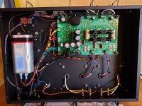
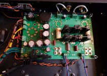

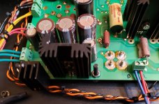
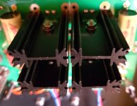
So here are better pics of heat sinks. The tall ones on mosfets had to have fins where they come together milled off so they were not in contact. The mount pins dont fit the board holes so they are potted to the board and the traces on board were cut to keep them all isolated. Used thermal paste on them.
The regulator IC sink is even bigger and had to be milled to clear caps. All those heat sinks are like 2" tall and have a lot of mass. Havent had overheating issues yet.
And the orange and black twisted pairs are how I am feeding the current to the front meters.
The regulator IC sink is even bigger and had to be milled to clear caps. All those heat sinks are like 2" tall and have a lot of mass. Havent had overheating issues yet.
And the orange and black twisted pairs are how I am feeding the current to the front meters.
Attachments

What current meters are you using, and how are you powering them? The measurement points are at B+ potential and the usual voltage sources are ground referenced, this puts nearly 400 volts across a meter of unknown quality.
So I am using these from Murata
DCA-20PC-4-DC4-RL-C Murata Power Solutions | Mouser
They take an external DC power supply and are isolated so just using a little 12v wall wart coming in through the back and switching it with DPST power switch. Gives me enough DC for a small fan if I want but havent needed one yet.
DCA-20PC-4-DC4-RL-C Murata Power Solutions | Mouser
They take an external DC power supply and are isolated so just using a little 12v wall wart coming in through the back and switching it with DPST power switch. Gives me enough DC for a small fan if I want but havent needed one yet.
Thanks. Those meters are isolated to 500 volts and will work fine.
Someone suggested the use of those $3 meters seen on the Chinese web sites and I strongly advised against their use. I did order some for experimentation, but your solution is the safest choice.
See posts #879 through 885 here:
After a 14 year run, the TSE must DIE!
Someone suggested the use of those $3 meters seen on the Chinese web sites and I strongly advised against their use. I did order some for experimentation, but your solution is the safest choice.
See posts #879 through 885 here:
After a 14 year run, the TSE must DIE!
Yeah - they arent cheap but given how much I spent on the amp all told - it seemed like a reasonable idea. I would never put a $3 anything in something pushing 400V. I dont keep a fire extinguisher that handy...
I would never put a $3 anything in something pushing 400V.
I'm thinking about floating the whole thing off of the B+ supply. This way the entire guts are all at B+ voltage or slightly less. The only stress points would be the case.....but the cheap $2 meters I have coming have no case. For now it's just "don't try this at home kids" experiments to test the concept.
I dont keep a fire extinguisher that handy...
I do, ever since I had an OPT turn into an instant fireball back in the 80's. I was squeezing more than 170 watts through an "80 VA" guitar amp quality OPT on 750 volts of B+ when the Radio Shack load resistor went open leaving the amp unloaded at full power.
I got a new fire extinguisher and a pair of 500 watt load resistors after that incident.
The 5842s are the ubiquitous Raytheons that are the easiest to find right now. The 300bs are Genalex. Seem to be pretty solid for the price. Looked into some of the pricier remakes but havent done more than look.
All - might be poor form to sell things here but wanted to alert everyone here to me selling my TSE II partial build. If you are thinking about starting one this might be good start. (hope its ok given specific interest to this forum)
https://www.diyaudio.com/community/...ers-tubelab-seii-parts-board-for-sale.396959/
https://www.diyaudio.com/community/...ers-tubelab-seii-parts-board-for-sale.396959/
A few Tubelab amps, partial builds and parts have been seen for sale here, but this one set a record for quick sale, less than one hour. I see no problem posting occasional surplus TUBELAB items here, but this should not morph into a swap meet for assorted electronics as we already have one.
It has been said that all good things must come to an end, and it looks like that applies to Tubelab Inc, the company as well. Unless things change a lot, I can no longer afford to subsidize Tubelab out of my personal finances, so Tubelab Inc will likely cease operations at the end of 2023. The parts shortages, the economy, and the highest lost or severely delayed delivery services (mostly the USPS) I have ever seen have combined to make 2022 a serious money loser for Tubelab Inc. The start of 2023 is worse.
I'll probably list some of my excess "stuff" that directly applies to Tubelab boards here as well. All generic audio related stuff will get listed in the Swap Meet section of diyAudio.
Well thats definitely bummer news!!! You have given a lot of us here, myself included, a lot of time and energy to make this really cool audio gear possible.
Maybe someone will step up and take over?
Thanks for everything George!!!!!
Maybe someone will step up and take over?
Thanks for everything George!!!!!
Here are some more Tublab SEII and closely related items for sale - if anyone is interested:
https://www.diyaudio.com/community/threads/tubelab-tse-ii-board-for-300b-mostly-assembled-uk.403828/
https://www.diyaudio.com/community/...100ma-into-8ohm-1db-25hz-to-25-khz-uk.403830/
https://www.diyaudio.com/community/threads/tubelab-tse-ii-board-for-300b-mostly-assembled-uk.403828/
https://www.diyaudio.com/community/...100ma-into-8ohm-1db-25hz-to-25-khz-uk.403830/
- Home
- More Vendors...
- Tubelab
- Tubelab SEII Chassis