Hello Everyone I am a total noob at diy audio and I am looking to start my first project.
I have chosen dayton audio Dayton-Audio-ND28F-6 tweeter and Dayton-Audio-DC130A-8 as woofer as these are the only ones available with all the frd data and are in my budget.
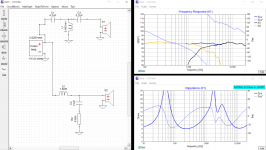
Tried my hand at desining a crossover and came up with a pretty flat looking curve, however i have no idea how to read impedence chart and wheather my design is feasible or not.
I am looking for inputs on my crossover design.
thanks
I have chosen dayton audio Dayton-Audio-ND28F-6 tweeter and Dayton-Audio-DC130A-8 as woofer as these are the only ones available with all the frd data and are in my budget.
Tried my hand at desining a crossover and came up with a pretty flat looking curve, however i have no idea how to read impedence chart and wheather my design is feasible or not.
I am looking for inputs on my crossover design.
thanks
Attachments
i think it is great that there are newcomers to this lifelong hobby! 🙂
regarding your project i can not say much, i have not worked with any of the drivers
but, often when you use measurements done by others they lack accurate phase responses and accurate phase is critical to make a good crossover. you could try estimate driver time differences by using the 'mod delay' feature in xsim to the driver furthest away from you or mic
also, when you present frequency response graphs it is a good idea to have the responses in the upper part of the graph, then we can see more what is going on to the responses in their down going slopes.
Here is a thread using the same woofer and a tweeter close to your price (on sale now).
I learned a lot about the crossover design process following the thread and then building a set of the speakers, They work really well for a small speaker that can be placed close to a wall.
Part of the balanced sound is like Celef points out due to the accurate phase response.
I learned a lot about the crossover design process following the thread and then building a set of the speakers, They work really well for a small speaker that can be placed close to a wall.
Part of the balanced sound is like Celef points out due to the accurate phase response.
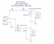
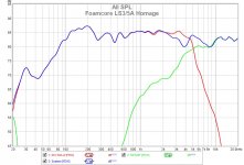
I have a design for the DC130A woofer and an RST28F. But I think it could be adapted for ND28F-6. The crossover is up near 5kHz so should be ok. This speaker sounds superb.
RST28F and DC130A Foamcore Homage to LS3/5A
RST28F and DC130A Foamcore Homage to LS3/5A
Attachments
i think it is great that there are newcomers to this lifelong hobby! 🙂
regarding your project i can not say much, i have not worked with any of the drivers
but, often when you use measurements done by others they lack accurate phase responses and accurate phase is critical to make a good crossover. you could try estimate driver time differences by using the 'mod delay' feature in xsim to the driver furthest away from you or mic
also, when you present frequency response graphs it is a good idea to have the responses in the upper part of the graph, then we can see more what is going on to the responses in their down going slopes.
Thanks i really appreciate the feedback but i dont have any testing equipments and i have a limited budget also I live in India and we dont get the choice that the west gets when it comes to diy.
The frd data is from parts express.
Ill try to put in delay next but i can only do simulated results as i dont have the drivers yet and also no equipment to test.
For now i am focusing on making the box for these.
I have limited set of tools so ill be taking these to a professional for rounding off the edges and getting it finished.
Hopefully ill be posting pictures of the final project very soon.
I have a design for the DC130A woofer and an RST28F. But I think it could be adapted for ND28F-6. The crossover is up near 5kHz so should be ok. This speaker sounds superb.
RST28F and DC130A Foamcore Homage to LS3/5A
RST 28-F is not available in india at a reasonable price, right now its out of stock but ill be getting components for both the crossovers.
Yours looks great. My design has impedence jumping off the charts any idea how can i get it to acceptable limits.
Thanks.
PS: I hope ill be getting some foam very soon.
I have a design for the DC130A woofer and an RST28F. But I think it could be adapted for ND28F-6. The crossover is up near 5kHz so should be ok. This speaker sounds superb.
RST28F and DC130A Foamcore Homage to LS3/5A
I am considering a vented box design.
Should I go for sealed instead??
Welcome to the hobby/obsession!
The DC130s are nice sounding mid-woofers, I use the DC130B in Curt Campbell's "Tritrix" speakers; I haven't used the ND28F.
Your crossover point seems to be about 2,000Hz, which might be a little low for the tweeter, going by its specs: the Fs (resonant frequency) is stated as 1097Hz, generally you want to cross a tweeter at at least 2x its Fs. That said, I did a Google search for projects which use that tweeter and they were both crossed at about 2,000 Hz, so there you go!
Geoff
Last edited:
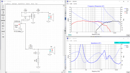
I tried crossing over around 3500k but i get a weird hump in the system curve which would make these really weird sounding.
Ill keep trying for now. Can you share the projects you looked into.
Thanks.
Ill keep trying for now. Can you share the projects you looked into.
Thanks.
Here are some projects which use the ND28, but different mids/woofers. It should go without saying that I haven't heard any of them.
Swope HT - undefinition
More love for the iron driver! Topped with the ND28 in a waveguide -
Techtalk Speaker Building, Audio, Video Discussion Forum
C-Killa RS150/ND28 TM is Finally Done! -
Techtalk Speaker Building, Audio, Video Discussion Forum
Of course, it won't be possible to use the crossovers and cabinet specs for any of these with your DC130s but if you read the write ups, you'll get an idea of the sound and how teh designers worked out what to do.
Good luck with your project
Geoff
Last edited:
Thanks.
Read through the posts and i think ill stick with the crossover for now but i will order extra components just in case i dont like the sound.
I really appreciate the help, thanks Geoff.
Read through the posts and i think ill stick with the crossover for now but i will order extra components just in case i dont like the sound.
I really appreciate the help, thanks Geoff.
You've made an excellent attempt at your 1st xo but please do not go with what you have come up with - the files you are using are not accurate simulations of your speaker yet.
To approach a decent level of accuracy, your sims need to take the raw frd and zma files and:
1 - add in the effects of putting the mid/woofer in a box (altho for a 2-way you can sort of skip this one),
2 - add in the effects of mounting them on a baffle,
3 - include the relative acoustic differences and then
4 - extract minimum phase from all your files.
So just quickly as 1 eg., go into the "Tune" sections for your drivers and hit the "derived" button. This will extract minimum phase from your files. For the FR, you have to 'tail' the response at each end which means you should choose a frequency and a slope that will extend the FR at both the top and and the bottom ends that will either extend the curve at the same slope it is currently displaying or match the slope that the spec sheet displays. Do that for both the frd and zma files for both your drivers and see how your xo looks. Changes will need to be made.
Here are some how to tutorials that are worth reading:
So you want to design your own speaker from scratch!
http://audio.claub.net/software/DaveDalFarra/Simple%20Loudspeaker%20Design%20ver2.pdf
FRD Consortium tools guide
Simulated Measurements - undefinition
Those provide a few different software choices I think that'll get the job done. For Dayton drivers, you can ignore subtracting the IEC baffle diffraction effects.
If that seems like too much, post your box alignment, baffle dimensions and driver positions and someone else can perhaps get your frd and zma files correct for you. It may help to know if these are going to be placed right up against a wall or in a bookshelf or on some stands further out in the room.
Guestimating the acoustic centers requires that you take measurements from the mechanical drawings in the spec sheets. For the tweeter, it's usually considered to be at the about the thickness of the faceplate. For the woofer, it's usually considered to be at the point where the voice coil meets the cone, which very frequently is where the spider attaches as well. I save the spec sheets to pdf files and then zoom in on them until the driver measurements on the computer screen are exactly physically correct and then measure to the point required. Then you want the difference between the 2 drivers which will change too depending on if the drivers are surface or flush mounted.
I would also second the idea of moving the xo frequency up a little bit. And/or attack the tweeter's resonant frequency with a capacitor in series with L1, the shunt inductor. Try a value of 43uF with your current inductor and see what kind of difference that makes.
For tailing, try to use as much of the drivers' real FR as you can or in other words, don't start the new tailing until the original FR stops.
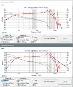
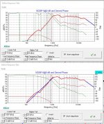
So for the tweeter LF tail, use about 100Hz instead of ~1000Hz. For the mid/woofer LF tail, use about 20Hz and a 6db/octave slope. For the mid/woofer HF tail, 20kHz is right but match the predominant slope that happens before that - in this case the slope between about 10kHz and 15kHz which is about -48db/octave. See pics below. Top pics are incorrect. Bottom pics are correct. In the case of the tweeter in pic 1, it only makes a small difference to the phase. But in pic 2 of the mid/woofer, the change is significant.
Why care? Because phase should be aligned in the region of the xo. So in XSim, turn off System Phase and turn on the individual driver phases (in the FR window, under the 'Curve' menu). Now try to align them in the region of the xo, about 1 octave above and below the xo point if you can. Your 1st xo did this fairly well. Your 2nd doesn't.
Still, you need to account for the other factors I listed above before your results are going to be a close approximation of the real thing. Please read the links I provided.
Attachments
Sorry, my bad. In my previous post I mislabeled the attached pictures. The top pics were correct and the bottom pics were the incorrect ones.
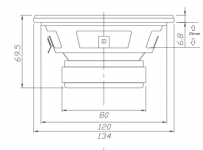
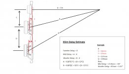
Although it may work out to be the same thing, you usually enter 0 for the tweeter delay and the relative difference between the 2 drivers for the woofer delay only. The diagram for the DC130 is not the best for locating the acoustic center but I would put it at about the lower edge of the frame cutout windows. I measure ~25mm if you surface mount it and ~32mm if you flush mount it. See pic below.
With XSim there is an extra step involved since you are actually trying to tell the program what the difference in path length is between the listening/imaginary mic position and each of the drivers' acoustic centers. Second pic below hopefully displays what I mean and how to calculate it. The pic is for a 3-way but you only need to concern yourself with the top 2 drivers.
So if the tweeter AC is 4mm back and the drivers are all flush mounted and the distance in height between the centers of the 2 drivers on the baffle is about 100mm and we use a mic distance of 1m, the delay for the woofer would be 1.29".
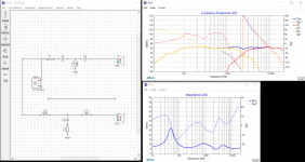
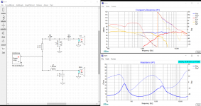
In terms of the above xo, the FR is flat and the phase is well aligned. However usually you want the 1st series component to be doing more of the work than the other ones. So all good on the woofer but not so good on the tweeter. Get C2 to do more of the work than C3. In particular, you can drop the impedance too low if you don't get this right.
I also like that the xo frequency has been raised but the tweeter resonance frequency of about 1100Hz is still less than 20dB down from the fundamental. That concerns me. You might want to try adding that cap that I mentioned before and see what it does when you center it at about 1100Hz.
Next include the baffle diffraction effects.
Although it may work out to be the same thing, you usually enter 0 for the tweeter delay and the relative difference between the 2 drivers for the woofer delay only. The diagram for the DC130 is not the best for locating the acoustic center but I would put it at about the lower edge of the frame cutout windows. I measure ~25mm if you surface mount it and ~32mm if you flush mount it. See pic below.
With XSim there is an extra step involved since you are actually trying to tell the program what the difference in path length is between the listening/imaginary mic position and each of the drivers' acoustic centers. Second pic below hopefully displays what I mean and how to calculate it. The pic is for a 3-way but you only need to concern yourself with the top 2 drivers.
So if the tweeter AC is 4mm back and the drivers are all flush mounted and the distance in height between the centers of the 2 drivers on the baffle is about 100mm and we use a mic distance of 1m, the delay for the woofer would be 1.29".
In terms of the above xo, the FR is flat and the phase is well aligned. However usually you want the 1st series component to be doing more of the work than the other ones. So all good on the woofer but not so good on the tweeter. Get C2 to do more of the work than C3. In particular, you can drop the impedance too low if you don't get this right.
I also like that the xo frequency has been raised but the tweeter resonance frequency of about 1100Hz is still less than 20dB down from the fundamental. That concerns me. You might want to try adding that cap that I mentioned before and see what it does when you center it at about 1100Hz.
Next include the baffle diffraction effects.
Attachments
Late Reply.
I was out of town for a few days.
I think ill order extra components for the crossover and try to mix and match, however, i have run into another problem of the amplifier.
Is a class d cheap chinese board good enough or should i buy one from a reputed brand like denon or yamaha.
Thanks, I appreciate all your help.
Why worry about a problem before it exists?
Build the speakers and get the xo right first. Then, if you don't like the sound with your current amplifier, then consider buying a better one.
Build the speakers and get the xo right first. Then, if you don't like the sound with your current amplifier, then consider buying a better one.
Would a 12 litres box with 6cm X 16cm port work for these drivers?
Yes, just is Xmax limited to ~10 W per hornresp
, so vent size can be smaller, shorter.
GM.
- Home
- Loudspeakers
- Multi-Way
- Dayton Audio Project for casual listening.