While trying to set the bias on any channel the amp starts pulling 8+ amps which puts my power supply into constant current mode. If I cycle the remote signal it returns to normal operation. It's like there are bad spots in the bias pots and when I turn the wiper over them the amp starts drawing current like a latching relay.
Could this be dirty pots or something else?
Notes:
Power supply fets were replaced with 3205's and 47 ohm resistors (this was the initial issue)
Power supply drivers were replaced as well.
Both gain pots have been replaced with 2.2k resistors. One was broken when I got it, I likely broke the other one.
Attachments
Confirm that there is no overlap in the drive signals from the opposing banks. Do this without B+.
Recheck with B+ when adjusting the bias as it starts to draw excess current.
Also monitor the DC voltage across each of the source resistors in the channel that you're trying to bias to confirm that the there is a significant increase in voltage as you try to increase the bias.
Did you do any work to the audio section other than the gain pots?
What do you mean that both gain pots have been replaced with 2.2k resistors?
I will test as you've outlined and report back.
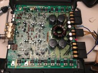
In the audio section I have done nothing but pull the gain pots, adjust the bias pots and compare component measurements with my meter between channels which included pulling 2 legs of each output to check for leakage. Not in that order but that is the complete, exhaustive list.
The gain pots are 5k, since they're both now broken I have 8 2.2k resistors in their place. One between pin 1 and 2 and a second between pins 2 and 3. This should be pretty close to having the gain pot set at halfway, correct?
As an aside, is it normal for resistors to be upside-down in these older Rockford amps? I can't read the value for about half of them.
It appears that adjusting the bias periodically upsets the PS drive.
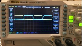
I had a very difficult time reproducing the latching behavior I described above but when I did the PS drive went screwy (picture #1 below.) The outputs had 0.00x across their current sense resistor and the PS FETs got hot fast despite being bolted to the heatsink.
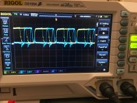
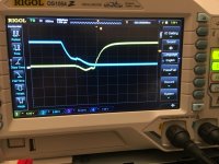
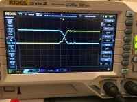
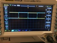
Adjusting the bias also alters the crossover (not sure that's the correct term) of the drive signals between banks. Picture 2- bias set full CCW. Picture 3- bias near factory position.
I had a very difficult time reproducing the latching behavior I described above but when I did the PS drive went screwy (picture #1 below.) The outputs had 0.00x across their current sense resistor and the PS FETs got hot fast despite being bolted to the heatsink.
Adjusting the bias also alters the crossover (not sure that's the correct term) of the drive signals between banks. Picture 2- bias set full CCW. Picture 3- bias near factory position.
Attachments
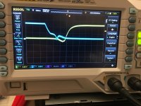
5us for the first picture (I believe that's generally what you specify for PS drive)
500ns for the 2nd and 3rd to see the change clearly. The transformer starts making noise when the drive looks as it does in the 3rd picture.
500ns for the 2nd and 3rd to see the change clearly. The transformer starts making noise when the drive looks as it does in the 3rd picture.
Do you see excessive ringing on the drains?
I forgot... Sometimes it appears that the resistors get packaged on the reels upside down and simply get placed that way. I'm assuming that you pulled at least one and saw markings on the other side.
I forgot... Sometimes it appears that the resistors get packaged on the reels upside down and simply get placed that way. I'm assuming that you pulled at least one and saw markings on the other side.
I don't have the frame of reference to determine what is excessive and what is acceptable. What I can say is the ring increases as the bias for any channel is increased.
Picture 1 and 2
All bias pots fully CCW, timebase 5us and 500ns respectively
Picture 3 and 4
All bias pots near factory position, timebase 5us and 500ns respectively
Ah, well that explains it. Yes, I did flip one over while working on the PS section. They're very hard to read face-down.
Picture 1 and 2
All bias pots fully CCW, timebase 5us and 500ns respectively
Picture 3 and 4
All bias pots near factory position, timebase 5us and 500ns respectively
Ah, well that explains it. Yes, I did flip one over while working on the PS section. They're very hard to read face-down.
Attachments


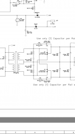
R12 and R55 are spot on.
C7 and C4 measure 0.0016uf which is 0.0006uf higher than spec.
I'll get C8 and R14 now.
C7 and C4 measure 0.0016uf which is 0.0006uf higher than spec.
I'll get C8 and R14 now.
R14 is spot on at 22.4 ohms
C8 is reading 0.56nf, basically double of the schematic which shows it being 270pf.
C8 is reading 0.56nf, basically double of the schematic which shows it being 270pf.
I don't think that's causing a problem but you should replace the cap if you have one.
With that snubber out of the circuit. is there any change in the behavior when adjusting the bias?
With that snubber out of the circuit. is there any change in the behavior when adjusting the bias?
I was asking about the rail cap. You specified leaving C8 out and testing.
I will leave them both out and test.
I will leave them both out and test.
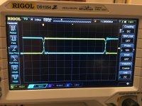
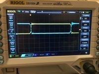
The ringing may be worse than before? It's also uneven but that may be due to the missing rail cap?
Pic 1 at full CCW pic 2 near factory bias setting.
I adjusted the timebase (2us) and position to show the uneven bits more clearly, still 10v per division. I can retest with the standard 5us if you prefer.
It was also much easier to get it to misbehave and "latch." Pictures 3 and 4 show two separate instances, each time a different bank got hot.
Attachments


- Home
- General Interest
- Car Audio
- Rockford 400a4