Hello, received this amp, blown output.
Removed all fets, installed new drivers, checked everything, seems ok.
Gate Signal on low side also ok.
Mounted new fets, it blows some fets directly.
Removed all fets again, new drivers, and checked with two fets, bank by bank. One side ok, if i mounted the fets on the other side, directly all drivers blown again.
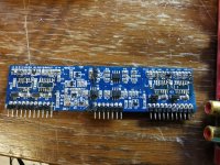
Removed fets and drive board again.
Checked the pins on the mainboard for the drive board. I have a saw tooth on pin 1, 10, and the 3.rd row, Pin 2 and 29.
I dont know what happened here
Removed all fets, installed new drivers, checked everything, seems ok.
Gate Signal on low side also ok.
Mounted new fets, it blows some fets directly.
Removed all fets again, new drivers, and checked with two fets, bank by bank. One side ok, if i mounted the fets on the other side, directly all drivers blown again.
Removed fets and drive board again.
Checked the pins on the mainboard for the drive board. I have a saw tooth on pin 1, 10, and the 3.rd row, Pin 2 and 29.
I dont know what happened here
Achim1409 Ground Zero GZPA 1.8K HC Hello, received this amp, blown output. Removed all fets, installed new drivers, checked everything, seems ok. Gate Signal on low side also ok. Mounted new fets, it blows some fets directly. Removed all fets again, new drivers, and checked with two fets, bank by bank. One side ok, if i mounted the fets on the other side, directly all drivers blown again. Removed fets and drive board again. Checked the pins on the mainboard for the drive board. I have a saw tooth on pin 1, 10, and the 3.rd row, Pin 2 and 29. I dont know what happened here Posting Rules
Attachments
Do you have a diagram (exact or generic) for the amp? The AQ20 is probably close, if not.
Did you check the drive signals before installing the FETs?
Did you check the drive signals before installing the FETs?
Yes, drive signals are there. I have no diagram, but its nearly the same as a DD Z1a or AQ..
Checked the voltages on Row 1 and 3... Voltages are roughly:
1: Mute
2: -130V
3: -150V
4: 0
5: 0
6: -150V
7:0
8:0
9: -150V
10: Mute
11: -150V
Row2:
1: -150V
2: Mute
3: -130V
4: -150V
5: 0
6: 0
7: -150V
8: 0
9: 0
10: -150V
11: Mute
Ground on sec. center
I think its ok..
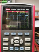
Amplitude for low side was ok on each Bank. Resistors ok...
Checked the voltages on Row 1 and 3... Voltages are roughly:
1: Mute
2: -130V
3: -150V
4: 0
5: 0
6: -150V
7:0
8:0
9: -150V
10: Mute
11: -150V
Row2:
1: -150V
2: Mute
3: -130V
4: -150V
5: 0
6: 0
7: -150V
8: 0
9: 0
10: -150V
11: Mute
Ground on sec. center
I think its ok..
Amplitude for low side was ok on each Bank. Resistors ok...
Driver board should have vcc +12v above negative rail for Vcc on the IRS chips. Is the voltage regulator in tolerance ?
IC's irs21844s - have max voltage of 20v.
IC's irs21844s - have max voltage of 20v.
Yes, the voltages are rouighly, if i check with mutlimeter, i have 128V and 140V, so that should be ok.
It's best to use the negative rail for the reference (black probe) when measuring the -R+12v (terminals 2 and 21).
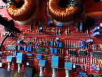
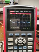
Could this be a problem with the output filter? I had only two mosfets inside this amp.. Osciloscope was shourtly showing a peak, like a building Amplitude, then i heared "tik" from the inductor.. AMp in protect, all irs are damaged.. the first two banks was no problem.
Last month i had shorted inductor in a similar amp. And it was visible only when i've pulled both of them and looked up closely at them from the bottom. There was no way to see it when they were being installed.
One of them was shorting and caused similar issues as You have described here.
One of them was shorting and caused similar issues as You have described here.
no, can i do this with the 9v Battery, and the rectifiers in place?
Wich pin was Positiv on the IRS?
And where i place the ground probe for Highside testing?
Wich pin was Positiv on the IRS?
And where i place the ground probe for Highside testing?
Last edited:
Connect it across 11 and 13. 13 is positive. You can connect it to the capacitor that's connected across those terminals.
You can leave the rectifiers in the circuit.
You can leave the rectifiers in the circuit.
- Home
- General Interest
- Car Audio
- Ground Zero GZPA 1.8K HC