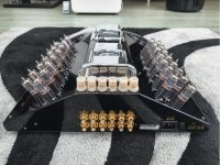
Looking at a EAR V20.
One channel has mains hum and crackling for about 2 mins from Switch on.
Only happens from 'cold'. If left over-night.
Once on and OK can be turned off and back on and will be OK. If left off for even an hour, will be OK.
All Valves (24x ECC83 + 2x ECC82) and Electrolytics replaced.
Still the fault remains.
Any thoughts appreciated.
P.
Assuming it must be a mechanical issue, possibly linked to the stresses of heating, then you could try tapping around the tubes and PCBs with an insulated pointer, and try and localize the issue.
Thanks for the reply.
To me, it doesn't sound that kind of crackling. But I'll do as you suggest and see what happens.
P.
To me, it doesn't sound that kind of crackling. But I'll do as you suggest and see what happens.
P.
freezing spray is good for this kind of problems.
One can direct the spray on a singel component.
One can direct the spray on a singel component.
There doesn't seem to exist any schematics diagram on the web. But I found a verbal description of the circuits of the V20.
www.technologydistribution.be/reviews/EAR/v20.pdf
Skip the blabla about the sonic properties, the "Technical Highlights" are on the last 3 pages.
It uses ten 12AX7 / ECC83 tubes (!) per channel as outputs in a PP configuration, five tubes or 10 small signal triode sections per phase.
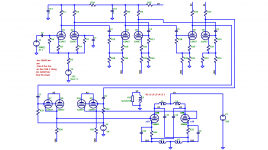
This caught my attention and so I took the description from the article and tried my best to convert it to a drawing of the circuits. I may not have figured every detail and of course I do not have any actual component values. A spice simulation with arbitrary numbers seems to work and I get reasonable signals from it.
The output stage is unity coupled, so the OPT requires dual primaries, one in plate circuits and one in cathode circuits similar to MAC but no bifilar windings are being used. The author of the article however erred when he assumes that this means cathode degeneration. As in the MAC and also in Norman Crowhurst's "Twin-Coupled Amplifier" this local negative feedback is cancelled by the positive feedback from bootstrapping the driver stage. The author also incorrectly describes the use of cross coupled capacitors in the output stage to make up for the lack of coupling between the primaries caused by not using bifilar windings as "devised by Mr. Paravicini". But Norman Crowhurst's article "Twin-Coupled Amplifier" from 1957 already described these capacitors as necessary to take care of the middle and high frequencies. https://www.audiofaidate.org/articoli/Crowth-twincoupled.pdf
www.technologydistribution.be/reviews/EAR/v20.pdf
Skip the blabla about the sonic properties, the "Technical Highlights" are on the last 3 pages.
It uses ten 12AX7 / ECC83 tubes (!) per channel as outputs in a PP configuration, five tubes or 10 small signal triode sections per phase.
This caught my attention and so I took the description from the article and tried my best to convert it to a drawing of the circuits. I may not have figured every detail and of course I do not have any actual component values. A spice simulation with arbitrary numbers seems to work and I get reasonable signals from it.
The output stage is unity coupled, so the OPT requires dual primaries, one in plate circuits and one in cathode circuits similar to MAC but no bifilar windings are being used. The author of the article however erred when he assumes that this means cathode degeneration. As in the MAC and also in Norman Crowhurst's "Twin-Coupled Amplifier" this local negative feedback is cancelled by the positive feedback from bootstrapping the driver stage. The author also incorrectly describes the use of cross coupled capacitors in the output stage to make up for the lack of coupling between the primaries caused by not using bifilar windings as "devised by Mr. Paravicini". But Norman Crowhurst's article "Twin-Coupled Amplifier" from 1957 already described these capacitors as necessary to take care of the middle and high frequencies. https://www.audiofaidate.org/articoli/Crowth-twincoupled.pdf
Attachments
Reading the description given in the EAR publication I get the sense that the output is simply a PP set of 10 or 20 12AX7s. So driven hard there could be some 10-20 watts of audio. Better results are usually got with low or medium mu triodes, 12AU7s would probably be a better choice.
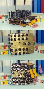
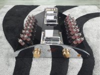
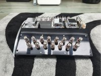
Reminds me of my looks a a many tube amp, I used 20 6AQ5s in a totem pole configuration. It required both plus & minus 300 volts PS, but made 100 watts. It was an experimental constant current output used to drive a synchronous motor. Output depended on the driving frequency into the inductive load. Then I got moved to a different project, that would be around 1960.😱
I kept the pile of electronics when I moved on, its still here on the shelf.🙂
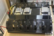
6AQ5 x20 Totem Pole Constant Current Amplifier
100 Watts at 120V AC drives Synchronous Motor, circa 1960.
Could be easily modified to Constant Voltage & drive a loudspeaker thru an OPT.😀
100 Watts at 120V AC drives Synchronous Motor, circa 1960.
Could be easily modified to Constant Voltage & drive a loudspeaker thru an OPT.😀
Attachments
Last edited:
or 6n1p 's ...Reading the description given in the EAR publication I get the sense that the output is simply a PP set of 10 or 20 12AX7s. So driven hard there could be some 10-20 watts of audio. Better results are usually got with low or medium mu triodes, 12AU7s would probably be a better choice.
I got 13 watts from my sim, which is guesswork from the description.
But the major issue seems to be to find a solution not to over-steer the 3rd amplification stage. In my sim total THD stays under 0.03% until about 3.5 watts, above that it quickly rises to 0.3% at 5W and 0.8% at 10W. The sudden rise in THD happens exactly when the 3rd stage enters grid current. The two nested FB loops struggle to tame that, after all the open loop gain is actually 60dB and FB drops that to about 30dB. So the art seems to be to prevent the 3rd stage to draw grid current.
Or maybe that is the reason why in the original there are "resistors across the coupling caps adding a tough of DC coupling". I haven't found out yet how to do that though without disturbing bias altogether ...
This is a very interesting circuit. I had one amp in for repair these days.
As seen in post 5, a good description is in the attachment, pages 7 .. 9.
This text, unlike the test report there, was written by Bascom H. King.
Only one channel is shown, the supply is common to both channels.
Apparently the amplifier is balanced. Even the input could be wired in
symmetric balanced mode, but the V20 amp has RCA input sockets.
Obviously Tim de P. did not care to draw the 50k ALPS volume pot,
located right next to the input switch and wiper going to "+0", input
cap of the first grid.
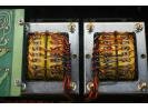
Both 10 µF caps coupling the output transformer windings are shown
with wrong polarity.
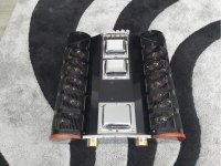
This transformer has an impedance Raa of about 1,25 kΩ and Rkk
1,25 kΩ also for unity coupling.
In this particular amp the driver cathode pull down resistors used have
been 5MΩ6 instead of 6MΩ8.
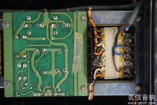
Ground scheme as seen in the amp is different from the drawing :
- Speaker output "0" is connected to chassis via uninsulated binding post.
- Signal and supply ground is connected to this point also (not seen in the
schematic).
- Safety ground, "G" in the diagram, was wired to chassis via 47Ω resistor.
This looked original but is not allowed in this area and I doubt elsewhere.
I think operation of this amplifier is very satisfactory from a technical point
of view. Look at the complete symmetry and nice ways of bootstrapping
and establishing dc balance. Square wave response is excellent and clean
compared to most other tube amplifiers.
I see this as a nice and simple alternative to "PPP" or Circlotron amps.
Claimed power output can be confirmed at about 25 W with nominal load.
Bias voltage as seen is about 8 .. 9 V for each cathode resistor for a plate
current of 7 mA per triode section - this was with a used set of tubes which
gave full output.
As seen in post 5, a good description is in the attachment, pages 7 .. 9.
This text, unlike the test report there, was written by Bascom H. King.
Only one channel is shown, the supply is common to both channels.
Apparently the amplifier is balanced. Even the input could be wired in
symmetric balanced mode, but the V20 amp has RCA input sockets.
Obviously Tim de P. did not care to draw the 50k ALPS volume pot,
located right next to the input switch and wiper going to "+0", input
cap of the first grid.
Both 10 µF caps coupling the output transformer windings are shown
with wrong polarity.
This transformer has an impedance Raa of about 1,25 kΩ and Rkk
1,25 kΩ also for unity coupling.
In this particular amp the driver cathode pull down resistors used have
been 5MΩ6 instead of 6MΩ8.
Ground scheme as seen in the amp is different from the drawing :
- Speaker output "0" is connected to chassis via uninsulated binding post.
- Signal and supply ground is connected to this point also (not seen in the
schematic).
- Safety ground, "G" in the diagram, was wired to chassis via 47Ω resistor.
This looked original but is not allowed in this area and I doubt elsewhere.
I think operation of this amplifier is very satisfactory from a technical point
of view. Look at the complete symmetry and nice ways of bootstrapping
and establishing dc balance. Square wave response is excellent and clean
compared to most other tube amplifiers.
I see this as a nice and simple alternative to "PPP" or Circlotron amps.
Claimed power output can be confirmed at about 25 W with nominal load.
Bias voltage as seen is about 8 .. 9 V for each cathode resistor for a plate
current of 7 mA per triode section - this was with a used set of tubes which
gave full output.
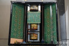
Some repair tips may be useful.
Input switch board and especially volume board interconnects to RCA
board can be damaged by rough handling of the respective rotary knobs.
This can be hard to repair. Missing signal ground is no pleasure here.
Lorlin made input switch may need lubrication. If the input switch fails
or only one input is required "Tape out" can be used as an input, see
diagram.
It is necessary to replace all 40 cathode caps. The tiny specimen used
here, albeit printed 105°C, are located close to the tube sockets and
deteriorate quickly. Leaking electrolyte can cause corrosion in some
places on copper side also. I recommend to solder replacements on
the other side of the board and used professional sealed mil types.
There is just one other radial lead cap, 47 µF 50 V which should be
replaced. All axial lead caps (Siemens etc) and all resistors except one
tested fine.
It is possible to unscrew and move the boards up for changing parts
without removing the wiring. Doing this and other work you can see
though that this construction is unnecessarily clumsy.
Filament wiring is on board with copper traces. Some of the traces are
too small, only 1 .. 2 mm here and there. Have a look for local signs of
overheating.
When doing repair take care not to confuse 2 driver tubes ECC82 with
the rest, all 13 of them are ECC 83.
Wow, I built the prototype of that amplifier, I was about to volunteer to try and remember the bones of it but that won't be necessary, thanks. It is all a bit hazy in my mind now anyway, interesting to look at the circuit again. Tim was all enthused by the 859 with its grid 2 drive, and wondered if he could do a similar thing with triode. I think he chose 83 because to make it work most of the time it would be drawing grid current i.e. enhanced triode.
Not that much, but I am pretty sure it started as a V12 (one of Tim's favourite engines, and I thought it had an extra bifilar winding for the 82 anodes, but I could be confused with the 509. And the style was strongly influenced by the Ford Ka, the first one which had just come out. I was more into the SE, still am, and was plotting my own build 859, which never happened unfortunately. Was impressed with the way it worked though, as an output stage, rather than the "enhanced triode" aspect. I don't know if it is possible to build better one. He did think it should be cheaper to re tube than a pair of 300bs, at the time.
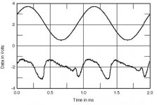
the residual distortion character (fundamental notched out) don't looks good - diagram of image No 9 and under
EAR V20 integrated amplifier Measurements | Stereophile.com
What could be therefore the reason ? Maybe not good matching ?
some images in the attachment.
EAR V20 integrated amplifier Measurements | Stereophile.com
What could be therefore the reason ? Maybe not good matching ?
some images in the attachment.
Attachments
-
 1283534034_0_g.jpg157.7 KB · Views: 208
 -
 1283534034_2_g.jpg140.6 KB · Views: 234
 -
 1511220442534826016.jpg76.2 KB · Views: 244
 -
 1511220443070647825.jpg4.5 KB · Views: 265
 -
 1511220442541990018.jpg66.8 KB · Views: 269
 -
 1283534034_5_g.jpg174.4 KB · Views: 259
 -
 1283534034_3_g.jpg133.8 KB · Views: 260
 -
 1511135573031674622.jpg78.8 KB · Views: 276
 -
 1511135572679383281.jpg58.8 KB · Views: 249
 -
 Earfig4.jpg18.2 KB · Views: 214
Last edited:
Distortion in Fig. 5 of this test report is taken at high power
and low frequency of 50 Hz and the dominant third harmonic
may indicate power limit / saturation.
and low frequency of 50 Hz and the dominant third harmonic
may indicate power limit / saturation.
I mean Fig. 4: (1kHz waveform at 2W into 4 ohms (top), distortion and noise waveform with fundamental notched out)
- Home
- Amplifiers
- Tubes / Valves
- EAR V20 Schematic wanted.