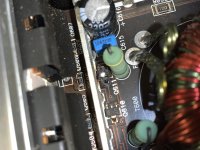
Was gifted a JL 500/1 monoblock amp. Once wired up, unit powers on but has 0 output (verified 0V AC, with headunit at 75% volume playing a 50hz test tone). Also tested another amp with no issues. I pulled the back cover and only visible damage is to the Q611 transistor.
Does anybody know of this is a common problem for these amps and if it’s worth the time investment to repair? Unit is probably 15 years old, but has sentimental value so I’d like to keep it alive if possible.
This is my first attempt at amp repair so I’d likely invest in the repair guide by Perry and buy some equipment to do it right, but not sure if I’m getting in over my head here. Have an ME degree and work in the aerospace field as an engineer, I’m fairly confident I can handle the work, but not sure if it’ll run into surprises along the way. Any advice is greatly appreciated on first steps.
Attachments
You'll have to decide if it's worth the effort.
There is likely much more damage. All of the power supply FETs are likely damaged. You can see the driver transistors are damaged. The PS FET gate resistors will likely all have to be replaced. The 10 ohm resistor on the edge of the board may be out of tolerance. That's the power supply
In most instances, the power supply fails because the output FETs fail.
I appreciate the quick reply and honesty, Perry. Definitely more than I was anticipating but then again I don’t know much. I’m fascinated by your site and guides, I’ll be reading up and doing my homework before I can decide if I’m up for the challenge. I’ve got the itch though so you’ll likely be getting an email from me in the next few days - interested in the full tutorials. Thanks again.
There are plenty of 500/1 threads on this forum. Those will give you an idea of what you're in for. That said, you can put it off until you have time for it.
While I can't help you with your repair I can share my point of view as a novice if you're interested.
If this is a one and done deal your money may be better spent just having the amp repaired for you. If you think it could become a hobby then dive in head first.
The most valuable piece of kit for getting started is Perry's tutorial. I wish I had bought it years ago, it's worth way more than he asks for it. I'll warn you though- it's dense and, if your experience is anything like mine, you'll have to read it cover to cover multiple times while getting familiar with the hardware. I actually need to read through it again and take notes now that I have an idea of what I'm doing.
A good soldering iron is mandatory. Components on large power and ground planes are impossible to remove if your iron isn't up to the task. Inversely, too much heat damages boards.
The last thing I'll say is this: you will get the absolute highest level of help if you answer all questions as succinctly as possible. If you're uncertain how to make a measurement, ask. It's far better to ask a stupid/obvious question than provide inaccurate information. If you make any changes to the board (removing, replacing or installing components) include that information.
Thank you both. I found myself staying up entirely too late last night watching old live streams of amp repair as well as reading every article I could find - I think I'm going to give it a shot. Worst case scenario I end up with a broken amplifier and learn a thing or two along the way which is more than I started with. I'm in no rush to get this done so however long it takes, it takes. I love solving problems and have had interest in audio for over 10 years at this point, I always find myself drifting back this way so I could see myself making a hobby out of it.
I'm currently in process of refoaming a JL 12W7 which I was going to buy a power supply for to do it correctly so if I can have another use for it all the better. I'll definitely need to invest in a better soldering iron as the one I have is a cheap RS brand as well as a better multimeter.
The only thing that concerns me is the cost of a scope, is this going to seriously hinder my ability to troubleshoot without one?
A scope is necessary to confirm that the shape of the waveforms is right. You don't need to spend a lot on a scope. I'd recommend an analog, CRT based scope. Ask around, one of your engineer friends may know where you can get one for cheap. Scope probes are cheap ($20/4) so they're not a concern.
Don't worry about the age of the scope if it works. Virtually any scope in good working order, made in the last 60 years will do the job. The thing to confirm on really old scopes is that it has a triggered sweep.
Don't worry about the age of the scope if it works. Virtually any scope in good working order, made in the last 60 years will do the job. The thing to confirm on really old scopes is that it has a triggered sweep.
I've actually had some luck in my search for a scope, seems like there are some pretty decent deals on my local CL - I may try my luck this weekend. However I am having some trouble finding a decent power supply that can deliver the 35 amps. Is 35 amps a hard requirement for this type of troubleshooting. This 500W amp powered with 14V DC is definitely capable of drawing the 35A, but what is the typical draw of just powering a board up. Am I silly to think I can get away with a smaller power supply, or should I save up until I can afford a high output PS?
For reference, I was looking at the PYRAMID PS52KX 46 Amp, amazon has it now for ~$230, but I'm wondering if the smaller models that deliver less power are higher quality?
I'm using a cheap ($60 shipped at the time) 10 amp power supply and rarely set it for more than 3 amps while working on a board. It's what I could afford when I was getting started. A higher wattage supply is absolutely necessary for stress testing though.
Edit:
I just looked at the PS you mentioned. It doesn't appear to have a current limiting function so you'll need a resistor between it and the amp. Perry can give you better advice than I.
Edit:
I just looked at the PS you mentioned. It doesn't appear to have a current limiting function so you'll need a resistor between it and the amp. Perry can give you better advice than I.
Last edited:
You need to test amps to full power to determine if they're functioning properly. It's best to do this on the bench where you can quickly shut down if there is a problem. To do this, a 35 amp supply is only good for smaller amps.
Small supplies can be used for low power testing and troubleshooting. I generally worked with a 25 amp supply, through a 2 ohm current limiting resistor (not useful on JL amps) where current limiting was needed.
If you work on larger amps, you'll meed much larger supplies to test at or near full power. That's where you get into batteries (fused, properly) and server power supplies.
Thanks guys, guess I should've read the tutorial before asking silly questions. This is all covered and looks like the Amp I was looking at comes recommended. The Pyramid should hopefully get me through this repair and I can upgrade as necessary. Appreciate all your feedback.
Any experience with the brand TekPower? I couldnt find much in the forums, but the specs look ideal and at a good price. Specifically models TP540E and TP50SW. They are both switching power supplies.
Also found a great deal on a Sony Tektronics 336A Oscilloscope locally, thinking I'm going to jump on it.
Switching power supplies can sometimes cause noise problems and can be more difficult to repair.
The dead simple linear supplies have neither problem. I used Pyramid supplies for 30+ years and never had to do anything to them except replace rectifiers as far as I can remember.
For troubleshooting, you don't need high current. Features like current and voltage meters (both visible at once) and adjustable voltage are important for troubleshooting.
For high current, high power testing, switching supplies are perfectly fine.
Just about have everything I'll need to attempt this repair, so far I've gotten:
Pyramid PS52KX Power Supply
Fluke 17B Multimeter
Weller WP35 Iron, Flux pen, Kester 44 solder
Still searching for a reasonably priced scope, but have my eyes peeled.
I've also ordered new:
PS FETS (IRF3205PBF)
PS Drive Transistors (2SB1260T100R/2SD1898T100R)
47 Ohm Gate Resistors (CR1206-FX-47R0ELF)
Output FETS (IRF3710ZPBF) - Originals were not shorted, but cheap enough I'll replace them.
I noticed the snubber? resistors R666/667 are out of tolerance (measuring 67/160Ohm respectively). I'm having difficulty finding suitable replacements - does anyone know their true value? I'm assuming they are 4.8Ohm 1%, but the colors are so faded its difficult to read.
My plan was to replace the drive transistors since one is visibly burnt, all the gate resistors, and PS FETS first and then power up through a 10A fuse to see what happens. The output side looks in good shape, so I'm nervous that there is something else going on that made the PS fail.
No apparent shorts on capacitors as far as I can tell, however there is continuity between many of the PS transformer winding leads. Is there an easy way to verify if this is normal?
Last edited:
The outputs are not 3205s. Don't replace perfectly good parts.
You should buy a 100w, 2 ohm current limiting resistor. I'd suggest the tubular ceramic, wirewound type. Don't buy the small (generally gold) aluminum housed resistors.
Sometimes the power supply alone fails.
It's normal to read 0 ohms across all primary windings. The same goes for the secondary windings. You're simply reading the resistance of a piece of wire.
Why do you believe that the snubbers are 4.7 ohms? They did use 4.7 ohms in some amps. I only have photos of the later 500s showing those resistors and they have 2.2 ohm snubbers.
My mistake, the IRF3710ZPBF is what I have down for the outputs, but I will hold off on ordering them if you think it’s unnecessary.
I’ve tried to attach an image of R666, the 4.8 ohm is my best interpretation of the colors. I have seen people reference 2.2 ohm for this resistor, do you think I can get away with some of those?
R666 - Album on Imgur
I’ve tried to attach an image of R666, the 4.8 ohm is my best interpretation of the colors. I have seen people reference 2.2 ohm for this resistor, do you think I can get away with some of those?
R666 - Album on Imgur
An externally hosted image should be here but it was not working when we last tested it.
Last edited:
Weren't the original outputs IRF540s?
Neither will make a difference, compared to the other. You can use 4.7s. Have you tried VERY lightly scraping the color bands to see of the color was intact below the surface?
When looking at resistors, the number of bands can help narrow it down. You can see that there aren't enough bands to be tight tolerance (1%) so it's likely in the E24 series. There is no 4.8 in that series. It would be 4.7 ohms. << shown in sections 1 and 2 on the 'Resistors and Capacitors' page of the tutorial if you have it.
- Home
- General Interest
- Car Audio
- JL 500/1 Rev 2 No Output, worth repair?