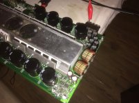
Amp came in for repair.
Kind-a works but the output is heavily distorted and doesn't even look like a sinewave. No power light on, no protect (LEDs work, tested them outside of the board).
It's the big brother of MTX 7801. I've checked your guide Perry and followed everything through it.
Optocouplers, N5532, rail voltage, supply voltages are all fine. Oscillation is as it should be according to the Perry's manual. I've re-soldered the inductors just to be sure. I've used jumpers to preamp bypass.
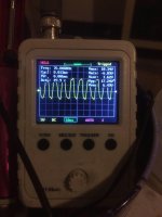
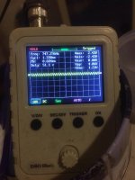
From the pictures:
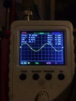
The clean sinewave is taken at the jumpers.
The distorted one is at the output of the amplifier.
It's the same if i re-connect the pre-amp section.
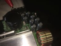
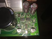
I've noticed that the output filter caps get warm. They are nichicon 63v 470uf, doesn't seem they have been changed but in Perry's guide the ones over there are Panasonic, but the voltage and capacitance can't be seen.
I took out 2 caps and measured them - they read just fine 501uf, ESR=0.1ohm (leads resistance not taken out).
What else to look for ?
Kind-a works but the output is heavily distorted and doesn't even look like a sinewave. No power light on, no protect (LEDs work, tested them outside of the board).
It's the big brother of MTX 7801. I've checked your guide Perry and followed everything through it.
Optocouplers, N5532, rail voltage, supply voltages are all fine. Oscillation is as it should be according to the Perry's manual. I've re-soldered the inductors just to be sure. I've used jumpers to preamp bypass.
From the pictures:
The clean sinewave is taken at the jumpers.
The distorted one is at the output of the amplifier.
It's the same if i re-connect the pre-amp section.
I've noticed that the output filter caps get warm. They are nichicon 63v 470uf, doesn't seem they have been changed but in Perry's guide the ones over there are Panasonic, but the voltage and capacitance can't be seen.
I took out 2 caps and measured them - they read just fine 501uf, ESR=0.1ohm (leads resistance not taken out).
What else to look for ?
Attachments

What does the rail-rail oscillation look like (before the inductors)?
Have you measured the DC voltage across terminals 5 and 8 of the optocouplers?
Have you measured the DC voltage across terminals 5 and 8 of the optocouplers?
The waveform is shifted up, it appears. Are the positive and negative rails equal?
Are the terminals of either output inductor broken?
Are the terminals of either output inductor broken?
Rail voltages are equal -+ 81v
Inductors are OK.
The waveform is shifted up, it appears - yeah kind-a yes.
Inductors are OK.
The waveform is shifted up, it appears - yeah kind-a yes.
Is LED400 lit?
Have you tried replacing the 5532 nearest the optocouplers? They can fail in a way that causes strange problems.
Have you tried replacing the 5532 nearest the optocouplers? They can fail in a way that causes strange problems.
Yes it is lit.
Haven't tried replacing 5532 as i don't have them in SMD package, only DIP in stock. Will order couple of them.
Haven't tried replacing 5532 as i don't have them in SMD package, only DIP in stock. Will order couple of them.
I've changed the 5532 - same, no difference.
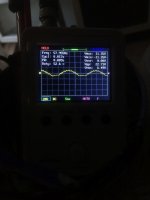
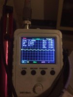
But i've noticed something interesting. When i turn on the amp, while it's starting up, there is a moment for a split second, just right before the amp turns on fully, the output looks kind-a better - picture attached.
Can't figure out if this is due to the filter circuit unable to filter out the noise or it's class D drive related.
Attachments
What do you mean by 'before the amp turns fully on'? What are you using as an indicator that it's fully on?
Where was that waveform taken (precisely, where were the probes)?
If on the speaker terminals, loaded? With what?
Where was that waveform taken (precisely, where were the probes)?
If on the speaker terminals, loaded? With what?
Fully on - when current draw stabilizes at 4.5A. This is what i'm referring to.
Between initial current surge and the stable 4.5A draw, in this timeframe i've taken the picture.
Waveform is taken at the output terminals with no load attached.
Between initial current surge and the stable 4.5A draw, in this timeframe i've taken the picture.
Waveform is taken at the output terminals with no load attached.
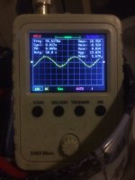
Dummy load attached - 2ohms.
First picture is without any RCA signal in. I don't know if this is the class D switching...
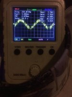
Second picture is 40hz sinewave into the RCA, but doesn't look like 40hz sinewave at the output.
It's a clean sinewave at the jumpers.
First picture is without any RCA signal in. I don't know if this is the class D switching...
Second picture is 40hz sinewave into the RCA, but doesn't look like 40hz sinewave at the output.
It's a clean sinewave at the jumpers.
Attachments
What does it sound like?
It's hard to tell exactly what we're seeing due to the limited bandwidth of the scope.
It's hard to tell exactly what we're seeing due to the limited bandwidth of the scope.
Okay...It sounds about right and it's interesting how these sub amps can play full-range but the pre-amp section limit their upper bandwidth.
Something else i've noticed. Even only after 15 minutes of low volume playing with 4 ohm subwoofer the inductors and the the output filtering capacitors get hot. Not warm but hot, especially the inductors.
Another thing to mention is when remote is applied and amp starts up, there is a squealing sound for 2 seconds through the speaker.
Besides that amp sounds just fine.
Are the fans working?
Generally, when driven hard, the fans (with the cover on) cool the inductors better but they do run hot. If they're both heating equally, they're likely OK.
I wouldn't expect the caps to get 'hot'. Have you pulled 1 or 2 to check them?
Does the amp squeal before LED400 lights up?
Does it do it with the preamp board bypassed?
Fans works in relation to the amount of "gain". But they work fine.
Both inductors heat up equally.
Caps get warm, yes, but they read fine - i've tested couple of them out of the board.
The amp squeal no matter if the pre-amp board is bypassed or attached, both ways is the same squeal sound.
Does the amp squeal before LED400 lights up? -- I'll have to pull the amp apart again to check for this...
- Home
- General Interest
- Car Audio
- MTX Audio TA81001 Thunder output issues