Rectifiers are out of circuit:
Good drive going to PS fets when they are out of circuit.
When Fets are in circuit the amp draws extreme hi current.
Assume bad transformer? Wiggle it as much as I can but no change.
Is the only way to verify shorted trans to remove from circuit and find physical short?
Good drive going to PS fets when they are out of circuit.
When Fets are in circuit the amp draws extreme hi current.
Assume bad transformer? Wiggle it as much as I can but no change.
Is the only way to verify shorted trans to remove from circuit and find physical short?
Do you have an oscilloscope? post a pic of the FET drive waveforms. Also of the PS section - both sides of the PCB.
Was the power supply repaired? FETs/FET drivers replaced?
Normally, wiggling the transformer and looking at the current draw will tell if shorted or not. you can look for corrosion (white powdery or black for arcing) where the windings overlap as a tell tale sign.
Was the power supply repaired? FETs/FET drivers replaced?
Normally, wiggling the transformer and looking at the current draw will tell if shorted or not. you can look for corrosion (white powdery or black for arcing) where the windings overlap as a tell tale sign.
What value are the gate resistors? I’ve made the absent minded mistake of using too high a value before, which causes slow turn off and high current consumption.
It's always good to know the amp make/model. There are lots of different drive circuits.
Working through a current limiter can sometimes allow the amp to power up just enough to find the fault.
Did you test the drive for the FETs with a loading capacitor to see if the drive was good before installing the FETs?
Working through a current limiter can sometimes allow the amp to power up just enough to find the fault.
Did you test the drive for the FETs with a loading capacitor to see if the drive was good before installing the FETs?
I will try to answer all-
Fets tested ok out of circuit.
Amp is Kicker CXA 1800.1.
Did not load the fet drive circuit with a cap to test.
Does anyone have any drawings of this amp?
Fets tested ok out of circuit.
Amp is Kicker CXA 1800.1.
Did not load the fet drive circuit with a cap to test.
Does anyone have any drawings of this amp?
If you would have included the make/model in the subject, PapaZbill (Kicker tech) would likely have helped (better than anyone else could). See if you can get a moderator to change the subject. If not, PM PapaZbill for help if he doesn't see your post.
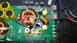
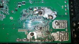
post good pics of board, top side.One overall and one close up of the power supply.
If you have an oscilloscope, post screen shots of the drive at the gate resistors and IC16-UC3843at Pin 4(PWM/Triangle) and Pin 6(Drive).
Post DC voltages around IC16 using power ground for the black probe.
Use should have two gate resistors for each IRFB4110, a 39 ohm and 2 ohm. Check that each are in value and connected through to the Mosfet gates.
I can't say I have seen a shorted T1. This problem is usually caused by a failed surface mount capacitor in the PWM/RC timing circuit namely C124-2nF or C122-470pF
All gate resistors check out fine.
IC16 voltages with fets out:
IC16 1 7.6v 8 5v
2 2.4v 7 11.3
3 .9v 6 .6v
4 1.9v 5 0v
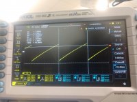
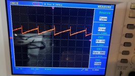
The waveform with the fets in circuit are with the power supply trying to start the amp up with excessive current draw.
IC16 voltages with fets out:
IC16 1 7.6v 8 5v
2 2.4v 7 11.3
3 .9v 6 .6v
4 1.9v 5 0v
The waveform with the fets in circuit are with the power supply trying to start the amp up with excessive current draw.
Attachments
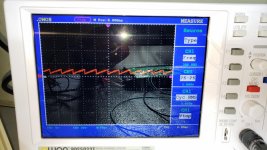

Where the Fets in or out of circuit when you captured the waveforms?
When the Fets are out of circuit is the amp able to power up?
When posting DC voltages use this format
IC16
Pin 1
Pin 2
Pin 3
Pin 4
Pin 5
Pin 6
Pin 7
Pin 8
Also when capturing waveforms open the Volts/div and Time/div up more to fill up the screen and get more detail. Use your cursors to measure frequency and P-p voltage
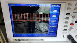
Where the Fets in or out of circuit when you captured the waveforms?
Sorry -
- the waveform with no deadtime is with fets in.
-the waveform with almost all deadtime is fets out
When the Fets are out of circuit is the amp able to power up?
Yes powers up with no fets in.
The sawtooth is Pin 4 of IC16. The other waveforms are Pin 6 and at the gate as they are identical.
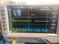
The waveforms attached are from a CXA1200.1. The CXA1800.1's little brother, w/o the mosfets.
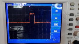
If you capture the waveforms so that I can see detail and frequency or time base I can better access the amp.
Looking at the sawtooth waveform you posted, it appears to be 330 hz(should be 49.8khz) which, if it is, will be the problem. C124-2nF or C122-470pF will have failed.
The two attachments(waveformsb and waveformc) of the drive from IC16-pin 6 are at pin 6 and the mosfet gate resistor after Q5-2045 gate driver IC.
Attachments
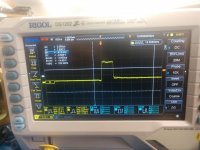

Sorry,It's been a busy couple of days.
Both the drive and sawtooth look good and the frequency is spot on.
If you have a fresh set of mosfets IRFB4110, install them w/o the rectifiers installed. If you have a current limiter use it and see if you can safely power up the amp.
Both the drive and sawtooth look good and the frequency is spot on.
If you have a fresh set of mosfets IRFB4110, install them w/o the rectifiers installed. If you have a current limiter use it and see if you can safely power up the amp.
I just realized you have IRF3205 in place of the IRFB4110. This is most likely what's causing the excessive current draw. Is this how the amp came to you?
Yes, that is how it came to me. IRFB4110 will have to order. Can you tell me the correct rectifiers, so I can check that also?
Here is a link for the 60CTQ150 rectifiers. If the ones you pulled from the amp are the same and check good, they should be fine. The link below is from Arrow, despite the recent thread they are a good source and I use them when I can.
They also have the IRFB4110 link below
https://www.arrow.com/en/products/vs-60ctq150-n3/vishay
https://www.arrow.com/en/products/irfb4110pbf/infineon-technologies-ag
They also have the IRFB4110 link below
https://www.arrow.com/en/products/vs-60ctq150-n3/vishay
https://www.arrow.com/en/products/irfb4110pbf/infineon-technologies-ag
Installed 4110's -issue remains.
The 6 pin gate driver for the PS fets. Should the collectors be driving the gates, or the emitters? Do you have a drawing I can use?
The 6 pin gate driver for the PS fets. Should the collectors be driving the gates, or the emitters? Do you have a drawing I can use?
the Q5-C2045ES gate driver uses the emitters. The NPN emitter driving the 39 ohm resistors and the PNP emitter driving the 2 ohm resistors.
I can't supply drawings due to company policy. I will dig out a datasheet for the 2045es and a source when I can.
I can't supply drawings due to company policy. I will dig out a datasheet for the 2045es and a source when I can.
Is the drive circuit similar to this:
https://www.diyaudio.com/forums/att...047-rockford-fosgate-prime-r1000-1d-power-pdf
https://www.diyaudio.com/forums/att...047-rockford-fosgate-prime-r1000-1d-power-pdf
- Home
- General Interest
- Car Audio
- General Power Supply Question