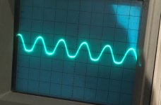
I'm working on a Parasound HCA-2200 (MKI). It is flattening the bottom of the sinewave in both channels at the same time, around 10W.
I've recapped the unit, except for the main filter caps. Someone had done a partial recap before. They had added an electrolytic cap across D105/106 and 205/206. I pulled it and didn't note the value. Probably should have. Not sure if it was supposed to be there and they had botched the wiring of replacement RCA jacks so I wasn't confident in their work. And was trying to fix a buzz (which was because I still hadn't gotten the RCA jacks wired right). Could it have been there for this reason? EDIT: looking at pictures in another thread where the caps are there. Guess I screwed up not keeping track of them. Anyone know what value they might be? I could email parasound again I guess. EDIT #3: In the MKII schematic it looks like there is 1uF capacitance here.
Where should I start looking?
Are the two trimpots at the input offset settings? If so how do I set them since there is two? EDIT AGAIN: Post #7 answers (Parasound HCA-2200 problem - need some help)
Schematic attached. Only the MKII schematic was online so I emailed parasound and they sent the MKI schematic.
Attachments
Last edited:
Any ideas? Adding the 1uF capacitor as mentioned in my post didn't do anything, and adjusting the balance (two trimpots near input) didn't do anything either.
Both channels do the same thing.
Both channels do the same thing.
First thing to test is the voltage rails are what they should be. If it affects both channels the power supply is the obvious place to start.
voltage on main caps is good.
Everything is dual mono.
Maybe related to whatever else the guy who was in here before did.
Everything is dual mono.
Maybe related to whatever else the guy who was in here before did.
Into what load impedance?I'm working on a Parasound HCA-2200 (MKI). It is flattening the bottom of the sinewave in both channels at the same time, around 10W.
Please post Volts RMS measured, then remove load (resistor/speaker) and measure again .
Same value as before or higher?
When output *just* starts clipping, in both cases, as now and without load, what do you scope on IC101 pin 7?
Measure supply voltage (pins 4 - 8) at IC101
Please post results.
Well, a new unknown variable was introduced.I've recapped the unit, except for the main filter caps. Someone had done a partial recap before.
I´d triple check each and every cap orientation, besides poor soldering, cracks, etc.
Maybe it was a Mod, but in principle amp should work fine with the .1uF cap shown there.They had added an electrolytic cap across D105/106 and 205/206. I pulled it and didn't note the value. Probably should have. Not sure if it was supposed to be there
Your schematic shows .1uF , the schematic you are NOT showing may show 1uF, who knows? In any case that´s a servo amp, no big change expected from one value to the other.and they had botched the wiring of replacement RCA jacks so I wasn't confident in their work. And was trying to fix a buzz (which was because I still hadn't gotten the RCA jacks wired right). Could it have been there for this reason? EDIT: looking at pictures in another thread where the caps are there. Guess I screwed up not keeping track of them. Anyone know what value they might be? I could email parasound again I guess. EDIT #3: In the MKII schematic it looks like there is 1uF capacitance here.
Where should I start looking?
See above.
Thanks, I'll check that soon. I was using an 8ohm load but will try it with no load.
Good to know that extra cap shouldn't matter too much.
I'm pretty good at recapping without causing any more issues.
Good to know that extra cap shouldn't matter too much.
I'm pretty good at recapping without causing any more issues.
Pretty confident. Tried the 1Khz signal from the signal generator, as well as off my ipad through a preamp just in case that was weird.
I've done lots of power tests before, not sure what I could have done wrong.
I realized that the amp has a 3 prong cord and I'd hooked the scope ground to - speaker terminal. But - terminal is grounded so that is okay I think. I need to watch for that though.
I've done lots of power tests before, not sure what I could have done wrong.
I realized that the amp has a 3 prong cord and I'd hooked the scope ground to - speaker terminal. But - terminal is grounded so that is okay I think. I need to watch for that though.
Use a 1kHz triangle waveform at clipping instead, and list the scope vertical V/div and probe attenuation factor.
Last edited:
Use a 1kHz triangle waveform at clipping instead, and list the scope vertical V/div and probe attenuation factor.
I'll connect the scope ground straight to the chassis this time too.
The triange wave should just make clipping a little clearer.
It wasn't quite clipping but a squashing of the wave.
I suppose it could still be something dumb.
Not sure about your signal generator, but if it is an app, earphone out usually can´t provide more than 200mV RMS, insufficient to drive a power amp which typically need 1000 to 1400 mV.
If generator clips, of course that will show up at output.
If preamp is fed lowish voltage rails (say, from a 9V battery) it will also be compromised, to be certain you need a 10X preamp, a simple op amp stage, which turns 100/200mV from a phone or tablet into 1-2V RMS, and it should be fed classic +/-15V rails, in which case it can put out up to 9V RMS.
But let´s start with simple measurements suggested, as-is.
Hi Racoon
Have you checked the power supply under load? I suggest isolating the power supply from the amp and connecting a ~50w & >100v light bulb across each rail that supplies the output stage. Then measure the voltages. You might have a dodgy rectifier (or bad connection) feeding one of the rails.
Cheers
Q
Hmm, Z101-102 are shorted in both channels so the input opamp isn't getting any voltage at all. This is embarassingly simple.
These zeners have 0.01uF film caps across them, as well as 100uf caps. How important is the value of the film caps? Schematic shows 0.1uF. They are twisted together so easiest to replace the film caps too.
These zeners have 0.01uF film caps across them, as well as 100uf caps. How important is the value of the film caps? Schematic shows 0.1uF. They are twisted together so easiest to replace the film caps too.
Last edited:
I looked at the schematic for the II version to compare the value of the bypass caps I mentioned in the last post. It has the electrolytic bypassed with a 0.1uF film cap and a 0.01uF cap. Overkill? My understanding of bypass caps is that the value isn't overly critical, so I used some 0.027 caps I had on hand.
Originally, these caps were mounted right above the zeners, so the zeners wouldn't have as much room to cool, and they would cook the caps. I opted to mount the caps to the bottom of the board instead.
I also removed the 6 parallel 0.01uf bypass caps on each main filter cap and put one 1uf cap in their place. Another thread was saying to do this. They were talking about the II version but still seems relevant for this one.
Amp seems to be working good now.
- Home
- Amplifiers
- Solid State
- Parasound HCA-2200 flatening sinewave at ~10W