Want a giant-slayer amplifier for short money? NAD built the 2600A and its twin the 2700 THX in large numbers. You can find one, maybe with some minor fault that reduces its price to beer-money territory.
This circuit does a lot of things right, right from the factory:
But can we do better? Can we improve its distortion performance by 20db? Will it kill Krells and mince Macs? You know it 🙂
Step 1: This amp comes with a built in preamp, a couple of JRC opamps that implement both the bridging switch and the front-panel volume knobs.
Even a 5532 is better than these opamps. Better yet, just remove R121 and R123 and jumper over them to defeat the preamp and run the "lab input" (aka "THX input") straight into the power amp section. Aaah that's better.
Deleting the bridging support is no sacrifice, as there's NO earthly reason to bridge this amp. With 92V rails, this amp is marginal for a 4-ohm load before bridging -- you're reaching deep into the SOA of the outputs to drive 4 ohms at anything near full rail voltage. Bridging it just makes this worse: 8 ohms becomes equally marginal and 4 ohms suicidal. Just don't.
Step 2:
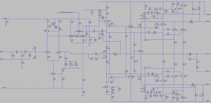
With a few substitutions, we can convert the factory circuit to TPC compensation. With two-pole roll-off in the loopgain, we can reach >55db of feedback in the audio band, instead of the ~35db we get with the factory circuit. See comments 5-7 and 22.
A word of caution, these PCBs have a very thin copper film. I often use the dremel to gently remove solder mask and clear off some copper, but that doesn't work well for the NAD -- the bit goes right through the copper to the fiberglass! :-C Ah well. If this was the kind of amp whose build quality audiophiles crow about, we wouldn't be hacking it up would we?
Step 3:
Adjust the input network and NFB network for reduced distortion and improved DC balance, see comment #9.
Step 4:
Add filtering on the +18V rail, and improve the IPS current source with an LED; see comment #15.
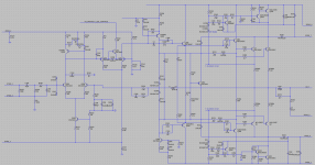
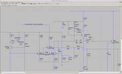
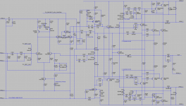
EDIT: First attachment is the stock circuit. Please ignore the 2nd attachment, which is an older rev of this mod. The "latest and greatest" circuit is in comment #22. Cheers!
This circuit does a lot of things right, right from the factory:
- degenerated IPS
- IPS loaded by a current mirror
- IPS doesn't directly drive either the VAS transistor or the miller cap. It's lightly loaded.
- triple EF output stage
- generous stability margins. (We need this when the OPS rails boost from 54V to 92V when the "power envelope" kicks in, that creates a blip in the output. That blip should settle and stabilize in less than 500nS, healthy stability margins allow this.)
But can we do better? Can we improve its distortion performance by 20db? Will it kill Krells and mince Macs? You know it 🙂
Step 1: This amp comes with a built in preamp, a couple of JRC opamps that implement both the bridging switch and the front-panel volume knobs.
Even a 5532 is better than these opamps. Better yet, just remove R121 and R123 and jumper over them to defeat the preamp and run the "lab input" (aka "THX input") straight into the power amp section. Aaah that's better.
Deleting the bridging support is no sacrifice, as there's NO earthly reason to bridge this amp. With 92V rails, this amp is marginal for a 4-ohm load before bridging -- you're reaching deep into the SOA of the outputs to drive 4 ohms at anything near full rail voltage. Bridging it just makes this worse: 8 ohms becomes equally marginal and 4 ohms suicidal. Just don't.
Step 2:
With a few substitutions, we can convert the factory circuit to TPC compensation. With two-pole roll-off in the loopgain, we can reach >55db of feedback in the audio band, instead of the ~35db we get with the factory circuit. See comments 5-7 and 22.
A word of caution, these PCBs have a very thin copper film. I often use the dremel to gently remove solder mask and clear off some copper, but that doesn't work well for the NAD -- the bit goes right through the copper to the fiberglass! :-C Ah well. If this was the kind of amp whose build quality audiophiles crow about, we wouldn't be hacking it up would we?
Step 3:
Adjust the input network and NFB network for reduced distortion and improved DC balance, see comment #9.
Step 4:
Add filtering on the +18V rail, and improve the IPS current source with an LED; see comment #15.
EDIT: First attachment is the stock circuit. Please ignore the 2nd attachment, which is an older rev of this mod. The "latest and greatest" circuit is in comment #22. Cheers!
Attachments
Last edited:
Let's look at performance.
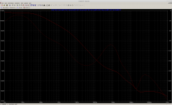
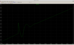
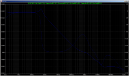
Transient sim into a 4 ohm load shows -108db distortion with the mod with a 400mV input signal, versus -85db with the original circuit. This level isn't enough to activate the boosted rails; distortion rises once we do, for both the modded circuit and the original.
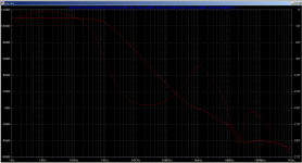
Loopgain plot with the mod is attached, as is the recovery from the OPS rail "jumping" to the "power envelope" voltage. (Pull-up recovery shown; pull-down is even better behaved.)
Transient sim into a 4 ohm load shows -108db distortion with the mod with a 400mV input signal, versus -85db with the original circuit. This level isn't enough to activate the boosted rails; distortion rises once we do, for both the modded circuit and the original.
Loopgain plot with the mod is attached, as is the recovery from the OPS rail "jumping" to the "power envelope" voltage. (Pull-up recovery shown; pull-down is even better behaved.)
Attachments
So how does this work anyway?
In the modded circuit, Q210 is a VAS buffer, it isolates the IPS from the nonlinear capacitance of Q302.
That's similar to the "honey badger" and other buffered-VAS amps... except this one has Q212 between the buffer and VAS transistor. Q212 is a cascode that lifts the voltage from ~9V to ~90V, reflecting its emitter current through to the collector. The 680p in parallel prevents its collector node from going high-impedance at HF. (Try the loopgain sim without the 680p: it does all kinds of wacky stuff around 10MHz, and the cap tames that.)
DR302 simply allows the 680p cap to drain at power-down without putting 90V onto the reverse-biased base of Q302. (In reality, Q302 would "zener" from base to emitter at around 5V of reverse bias, but IIUC this can damage transistors? So the diode protects it.)
The TPC network brings the compensation back to the IPS node. The beauty of TPC is that the IPS doesn't have to charge and discharge a cap: neither side of C210 has full output voltage, so it draws very little charging current. The IPS sees a super-light load with nearly constant current through both IPS transistors. (Ctpc2 has full output voltage across it, and it draws substantial current -- but only from the VAS so the impact is minimal.)
The 390k resistor in the TPC network prevents peaking around 1kHz in the loopgain plot. (It solves the same problem that Bob Cordell solves with a 2p or 3p cap from VAS output back to IPS, what he calls "bridged TPC.") There's no real advantage to using a resistor vs. a cap for this. There is a (small) advantage in connecting your 390k resistor (or 3p cap) to the output rail instead of to the VAS output node: the output rail is less distorted, and if we're going to expose the IPS to some current draw (as we must) we should pick the option that's less distorted. The effect is measurable on distortion sims, by just a few db. The output rail works just as well as the VAS output node from a loopgain plot perspective: to tame the peak at 1kHz, the output rail has basically equal phase to the VAS output node at LF. At HF where the output rail phase lags behind the VAS node, it doesn't matter since the 390k is swamped by the TPC caps at HF.
Last edited:
So there was actually a problem with this design!! That's what happens when you post on the forum, the OP always need some revision.
If we move the loop gain probe inside the loop formed by the 390k "Rsmooth" resistor, it's not smooth at all. Attached is the loopgain plot showing the peaking we're worried about. It's quite tall, something like 15db, nearly asymptotic, and right in the midrange of the audio band -- that can't be good. It's present through the VAS and OPS (not the IPS, phew) in the original design:
If we move the loop gain probe inside the loop formed by the 390k "Rsmooth" resistor, it's not smooth at all. Attached is the loopgain plot showing the peaking we're worried about. It's quite tall, something like 15db, nearly asymptotic, and right in the midrange of the audio band -- that can't be good. It's present through the VAS and OPS (not the IPS, phew) in the original design:
Attachments
In other TPC amps, I've tamped down this peak by degenerating the VAS a bit which makes it much softer but often still evident.
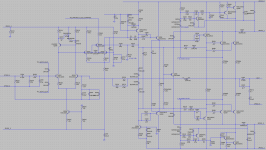
Here's a (novel??) solution that completely fixes the peaking, and its loopgain plot. I zoomed in on the VAS here since the rest of the circuit is the same as the factory amp.
Here's a (novel??) solution that completely fixes the peaking, and its loopgain plot. I zoomed in on the VAS here since the rest of the circuit is the same as the factory amp.
Attachments

For completeness, these are all changes from stock in "Rev B" of the mod:
One more reason to prefer Rev B: LTspice finds its DC operating point instantly, whereas for Rev A it will hunt for 10, 15, 20 seconds. That's a signal that the Rev A circuit isn't too well behaved.
- Delete C212
- Replace R228 with a jumper
- Replace R230 with a jumper
- Replace R302 with diode DR302
- Add Cmod5 (680pF) across Q212
- Add Rmod3 (820) from filtered top rail
- Replace C306 with C1 (39pF) + R1 (390k) in series
- Replace C210 with 68pF (it becomes part of the TPC network)
- Replace R218 with 2.7k (ditto)
- Add Ctpc2 (82pF)
One more reason to prefer Rev B: LTspice finds its DC operating point instantly, whereas for Rev A it will hunt for 10, 15, 20 seconds. That's a signal that the Rev A circuit isn't too well behaved.
I found improving the CCS using a green LED for the input stage to be effective in a Rotel and Hafler. Both has just a resistor though so the NAD is a step up already
Whoever designed the NAD did their homework pretty well, but one aspect of the stock design bugs me: the DC offset adjustment lets you choose between 0V DC offset at the output, or current mirror balance at the input, but you can't have both! At 0V DC output, the current mirror is something like 5% off of balanced.
With a few component substitutions in the NFB network, we can fix it so that current mirror balance and 0V output coincide, assuming matched IPS betas.
This is what I did:
Either this amp is really starting to sound sweet, or I'm just getting used to it. (It's the psychological effect of "burn in" -- DIY edition.)
With a few component substitutions in the NFB network, we can fix it so that current mirror balance and 0V output coincide, assuming matched IPS betas.
This is what I did:
- Replace C204 (the input coupling cap) with a nice Wima 2.2uF film cap
- Replace C226 (the NFB lead cap) with 10pF
- Replace R220 (smaller NFB) with 1.2k metal film
- Replace R226 (larger NFB) with a 22k Vishay RN -- this is a very good linear metal film part. I had a few lying around, and it happens to match the value of the 22k input network resistor for perfect DC balance.
- Reduce the TPC resistor from 2.7k to 1.5k, as the new loopgain plot showed some room to lighten the compensation a bit.
Either this amp is really starting to sound sweet, or I'm just getting used to it. (It's the psychological effect of "burn in" -- DIY edition.)
Attachments
Last edited:
Progress! Yes, NAD is well known for doing a darn decent job. Some criticism on reliability, but always sounded pretty nice. Proton was another we forget about.
From my experience, Self theory was very good, but I found pushing the numbers as in the Blameless was a bit , well, dull sounding. Temper his high feedback with a bit of Pass thoughts and a sweet spot emerges. A read of Cordell also helps.
From my experience, Self theory was very good, but I found pushing the numbers as in the Blameless was a bit , well, dull sounding. Temper his high feedback with a bit of Pass thoughts and a sweet spot emerges. A read of Cordell also helps.
Two minor updates.
Replacing R232 with something in the 15 to 39 ohm range boosts loop gain through the lower two-thirds of the audio band by ~5db with no evident downside. (Less than that, and a "shelf" appears around 10MHz that cuts into phase margin.) I used a 39 ohm part.
Secondly, I found a difference between my unit (2600A) and schematic (2700THX.) The NFB coupling cap C208 is 680uF on the schematic, 220uF in real life. Darn!! I haven't found ANY other differences, but we have to watch out.
Attachments
@tvrgeek
I've had mixed results pushing numbers. Sometimes the result sounds dull and sometimes it sounds involving, "you are there."
I used to believe that a circuit that produced super-low noise and THD on the simulator should sound great. I used to build TMC amps, with >60db of in-band loopgain around the output stage and >30db around the input stage. These amps (honey badger, etc) simulate with a distortion floor below 100db. That should be plenty. That should be inaudible... right?
Then I found that TPC sounds better than TMC. How can that be when the sim shows identical distortion performance?
TPC offers decades more loopgain around the IPS than TMC in-band, so a TPC input stage's currents make far smaller excursions from their DC operating points than the TMC amp's.
If you believe the simulator it doesn't matter. A TMC input stage's output current fluctuates by 50-100uA when it's working hard, moving the collector currents out of balance by ~5%. The sim says this input stage is linear to >70db in isolation and to >100db within the whole circuit.
I no longer believe the simulator for distortion numbers. My guess is there are parasitic effects in the IPS not known to the simulator, and switching to TPC for an extra 30db of feedback squashes them. But I'm not sure, this guess is based too much on listening.
sims can be a lot lower distortion then measured. they are not perfect past 0.005%
I tested my amp ( Valery's Litchstark) at a gain of 1(unity) and 10,000. both are very listenable except for hiss at 10,000. High frequency response is still detailed. I had to redo the mosfet drivers KSC3503,KSA1381 for stability.
the dual differential (NPN and PNP) pairs makes a difference to the sound.
Last edited:
To get better sounding amp, you need to tune it by ears, not with measurements. The first step is to higher the OL fr response. With TPC you reached 1khz, pull it to 20khz. You will get 20 times higher distortion at 1khz, but superior sound. You need complicated music to tune, I use since five decades, Happy Together of the Turtles, for first level. Requiems of Verdi and Mozart are for highest levels.
Last edited:
@tvrgeek -- thank you for the CCS suggestion! I finally got around to simulating PSRR for the +/- 18V frontend rails, and the not-so-constant current source showed up as a weak point.
Replacing R224 with an LED (I used an amber one, dropping about 1.8V) and replacing R212 with 470 ohms improves PSRR for the -18V supply by almost 20db.
With that done, the +18V PSRR was the new weak point. So I added filtering, replaced C216 with a 100uF and added a 150 ohm resistor before it.
One possible issue with the factory design -- the +/-18V power rails are coupled to ground by caps at two different places. That creates the possibility of a "ground loop" where AC currents can flow in the ground rail and the power rail and through both caps. These rails which have a 100uF cap on them at the supply and then another 470nF where they enter the main amp PCB. There's not much loop area, so it's probably benign, but still an antipattern. The added filter fixes it for the positive rail.
@kokoriantz
On the modded NAD, you can add a resistor across the bases of Q210 and Q212 to reduce the loopgain slope through most (or all) of the audio band to <6db/octave and phase to below -90. It's not quite flat but close. For example 1.5k ohms will do it. Loopgain at 20kHz and above is about the same either way.
I might try this on one channel to see how it sounds.
Bruno Putzeys agrees with you, he's written that it sounds better to have uniform loopgain through the audio band and not let it increase stratospherically. I have some amps that do this, and some that don't, but they're different amps and won't allow for an apples to apples comparison. This one might...
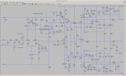
Here's the "final" circuit, incorporating all above changes. Until it changes again!
In other news, one of the relays was going bad. The trouble was revealed by connecting an AC voltmeter from the output rail to the speaker output. This would show many 10s of mV when tapping on the relay. Surprisingly I often didn't hear a change in the signal even when the DMM showed one! Perhaps I am going deaf, a deaf audiophile. Too much loud music.
So I have two TE Connectivity V23076A1022C133 on order. With luck that should be electrically and pinout compatible. Don't know why NAD chose automotive relays, or why two single-pole relays instead of one double-pole. It's this one, and I'll update this thread if it works (or not)
V23076A1022C133 TE Connectivity | Mouser
Attachments
The new relays (TE Connectivity V23076A1022C133) are not a perfect fit but they are close. I had to cut one pin off of each and drill a bit. Don't know if there's a perfect replacement for the original (Taiko PX-2405). At least these were cheap.
Thank you for sharing the trip 😉
A side question - do the component models (for transistors etc) that you have used in the simulations come with LTSpice or does one need to search for them in the net?
A side question - do the component models (for transistors etc) that you have used in the simulations come with LTSpice or does one need to search for them in the net?
@madis64
Some are Bob Cordell's models, some are manufacturer models. I haven't done any modeling myself -- the device physics are over my head.
The other interesting element you'll notice on the schematic is the loop-gain probe, which is from here.
Some are Bob Cordell's models, some are manufacturer models. I haven't done any modeling myself -- the device physics are over my head.
The other interesting element you'll notice on the schematic is the loop-gain probe, which is from here.
- Home
- Amplifiers
- Solid State
- Improve a NAD 2600A (aka 2700 THX) by 20db!