Hello Guys!
I'm restoring a luxman CL34 preamp and i d like your advice for the parts, here's the beast:
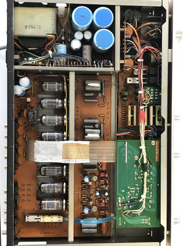
It is working properly but could benefit from a little refresh and improvements 🙂
I d like to start by the power supply

Bridge rectifier :
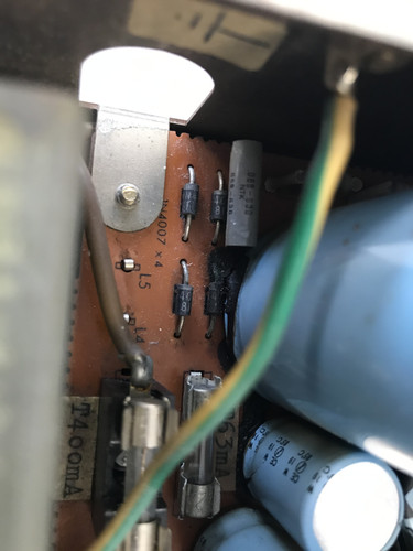
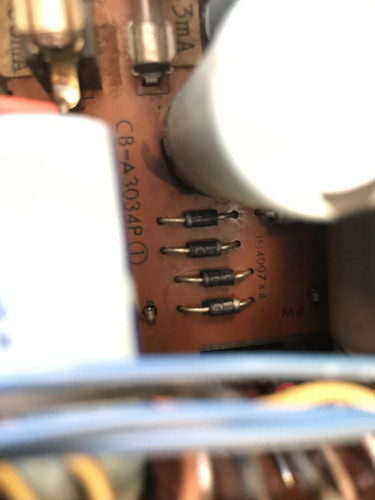
It is 1N4007 diode so i will swamp em for UF4007, i think it's an easy choice; less noise & faster
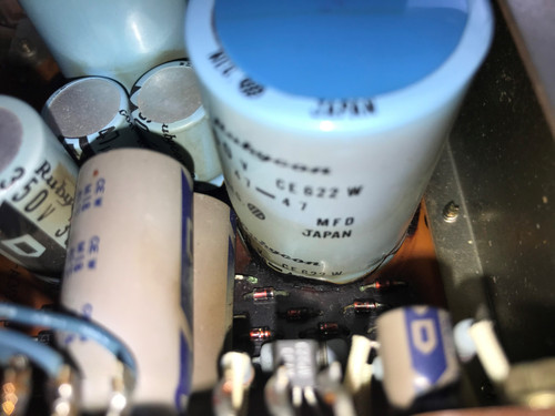
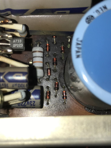
To continue with diodes, here's a bunch of WZ-310 above the second quad of 1N4007. Seems to dissipate a lot of heat !
I was thinking of BZX79C30T50A for the replacement and to mount them 5mm above the pcb to help with the heat. Any better choice or tips here?
Let's continue with the caps
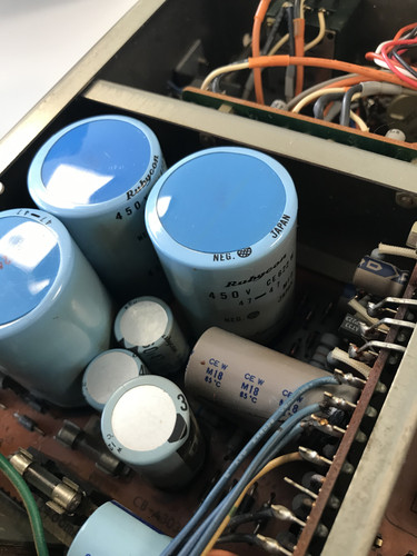
The big caps are 47uf+47uf 450V (35x50mm) here i could swap them for Mundorf Mlytic HV 50uf+50uf 500V
The others are 33, 47, 100 & 220uf from 16 to 350v, i guess i could use any good 105° power supply caps from panasonic or nichicon
The preamp board :
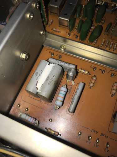
Most of the time i would not change that kind of film caps but the 15k ohms 2w ressitor on the right of the 1uf gray cap started to toast it so... let's swamp 'em all!
Here's the point is to find a good quality replacement for the 0.47uf 250v and 1uf 400v caps with quality and size in mind. PIO, Wax,... are too big.
I could change the resistor by a 15k 3w and take it away a little bit from the caps. Any suggestion here too?
Thanks for your help
Edit: bigger pictures
I'm restoring a luxman CL34 preamp and i d like your advice for the parts, here's the beast:
It is working properly but could benefit from a little refresh and improvements 🙂
I d like to start by the power supply
Bridge rectifier :
It is 1N4007 diode so i will swamp em for UF4007, i think it's an easy choice; less noise & faster
To continue with diodes, here's a bunch of WZ-310 above the second quad of 1N4007. Seems to dissipate a lot of heat !
I was thinking of BZX79C30T50A for the replacement and to mount them 5mm above the pcb to help with the heat. Any better choice or tips here?
Let's continue with the caps
The big caps are 47uf+47uf 450V (35x50mm) here i could swap them for Mundorf Mlytic HV 50uf+50uf 500V
The others are 33, 47, 100 & 220uf from 16 to 350v, i guess i could use any good 105° power supply caps from panasonic or nichicon
The preamp board :
Most of the time i would not change that kind of film caps but the 15k ohms 2w ressitor on the right of the 1uf gray cap started to toast it so... let's swamp 'em all!
Here's the point is to find a good quality replacement for the 0.47uf 250v and 1uf 400v caps with quality and size in mind. PIO, Wax,... are too big.
I could change the resistor by a 15k 3w and take it away a little bit from the caps. Any suggestion here too?
Thanks for your help
Edit: bigger pictures
Last edited:
Film and foil is preferable to metalized polypropylene (MKP), but your space constraints may force the use of MKP on you.
I came up with this for the 0.47 μF./250 WVDC part and this for the 1 μF./400 WVDC part.
Will these WIMA "monsters" fit and who actually has stock to ship?
I came up with this for the 0.47 μF./250 WVDC part and this for the 1 μF./400 WVDC part.
Will these WIMA "monsters" fit and who actually has stock to ship?
Your Luxman will not improve by using UF4007s instead of 1N4007s. There will be no difference as mains frequency is too slow to gain any advantage of fast recovery diodes, it is not a switch mode power supply.
Lifting power resistors away from the board is always a good thing but how old is it and how long do you want to keep it. Your photo does not show heavy damage after all these years.
PIO and Wax are notoriously electrically leaky and are trouble waiting around the corner. I always choose Panasonic/Nichicon/Sanyo/Vishay PET capacitors for signal, I doubt you will improve on what is already in place and the electrolytics should be kept to the same voltage and values if possible. Ensure they are reasonable quality however, I am servicing a Luxman SQ707 and the main smoothing capacitor has no measurable leakage and the capacitance is still 5% over original printed value, (the tolerance when new was +20% -10%), so they will stay in place.
On my customers Luxman, the smaller electrolytics are showing signs of ageing and are low value so will be replaced with Panasonic EECFU range.
For the 470n I would use Vishay MKT1813447405 and for the 1u Vishay
MKT1813510405 and the 15k resistor fit a 2W 5mm off the board but I doubt there will be any improvement . As you said, it is working perfectly, why break it?
Thanks for your answer, yes it is working properly. If the UF4007 wont change anything, i will leave it stock.
For the WZ diodes, i d like to improve the heat dissipation so i could find a replacement and take em away from the pcb a little bit, like the resistor near the film cap.
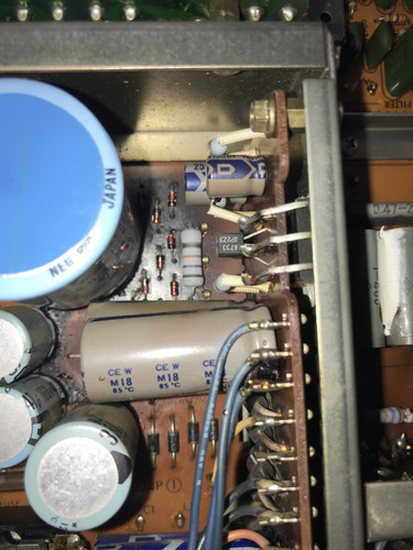
Here's a better picture of the little heat problem near the caps:
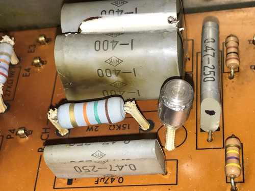
I d like to avoid that kind of cap frying. I could leave the 0.47 in place since they are not affected. I dont look after sonic improvement, just more reliability
For the WZ diodes, i d like to improve the heat dissipation so i could find a replacement and take em away from the pcb a little bit, like the resistor near the film cap.
Here's a better picture of the little heat problem near the caps:
I d like to avoid that kind of cap frying. I could leave the 0.47 in place since they are not affected. I dont look after sonic improvement, just more reliability
Last edited:
Your Luxman will not improve by using UF4007s instead of 1N4007s. There will be no difference as mains frequency is too slow to gain any advantage of fast recovery diodes, it is not a switch mode power supply.
I don't think Rick Miller, who did some testing and publishing on this subject, will agree with you. See (for instance) post #122: Simple, no-math transformer snubber using Quasimodo test-jig
That doesn't mean I hear these differences, but others say they do.
so what? this is a high voltage ldcrc filter for valve circuits...It runs at low currents and usually the secondary winding of the transformer is part of the filter...
It is only an opinion.I don't think Rick Miller, who did some testing and publishing on this subject, will agree with you. See (for instance) post #122: Simple, no-math transformer snubber using Quasimodo test-jig
That doesn't mean I hear these differences, but others say they do.
Some say they can hear a difference, in fast high slew rate amplifiers perhaps but most just think they can.
so what?
Just to point to the fact that you're not only dealing with the 50 Hz, but also with high frequency products caused by the diodes switching on and off. That's all. I don't think I would here the difference in a tube amplifier, but again, there are people who say they do. So if TS has the amplifier on the bench anyway...
In a tube preamp or amp you have to deal with high distortions rather than anything else.CL34 has a diamond buffer for headphones (discrete version of lh0002)and still they don't use any snubber on its low voltage rectifier filter as they have a capacitor multiplier which is slew rate limited by itself...not to mention that headphones themselves are slew rate limited by their electromechanical and inductive nature...
looking at Luxman's frequency response you can easily see it's limited by default so it won't reproduce any of those rectifier oscillations.
Actually if you look at Mark's answers to Rick you'll see that he's using AD811 to measure that ringing...that's 100 if not 1000 times faster than Luxman's circuit.
Luxman CL-34 on thevintageknob.org
This is one of the best audio product ever made...i wouldn't change a damn thing in the way Luxman's engineers did.
Last edited:
That doesn't mean I hear these differences, but others say they do.
Some say they hear the difference in oxygen-free copper cables 😀
i wouldn't change a damn thing in the way Luxman's engineers did.
I'll try to keep it as stock as possible and indeed will keep the 1n4007
I had the 'pleasure' of encountering a CL34 in bad need of repair.
The powersupply PCB was in an even worse state than the one shown in the thread.
Components are severely underrated, Zener-diodes and a power-resistor alike.
Finally parts of the PCB turned into carbon and the the amp. died.
Repairing the PCB and replacing burned parts restored life but the input IC-controlled servo acted up. Again parts were replaced including an IC but in order to make heads and tails on the input circuit I had to trace how the tubes are actually connected. This reveals a surprise or two, look for yourself in the attached pdf.
Good luck with getting this particular CL34 up to speed.
Rgds
Attachments
What people recommending high frequency , high voltage diodes forget to tell is that they also need to be at least 4 times higher current too because the the voltage drop is usually double on them when used in continuous mode.That also means twice the heat...and with that pcb...highly unlikely to last as the old 1n4007.
@tricomp thank you for your insight.I keep the tube set for ten years maybe i'll find the right time to make a cl 34 clone.I would have liked to have the CL40 schematic, but i couldn't fnd it for free.
Good luck with getting this particular CL34 up to speed.
Rgds
Thanks, do you remember what did you use to replace the WZ-310? It seems to be the hottest area in the CL34
What people recommending high frequency , high voltage diodes forget to tell is that they also need to be at least 4 times higher current too because the the voltage drop is usually double on them when used in continuous mode.That also means twice the heat...and with that pcb...highly unlikely to last as the old 1n4007.
This I don't understand completely. I can follow that the dissipation will be higher if the voltage drop (forward voltage) is higher. But are these differences between types of diodes not incorporated in their rating for maximum current?
- Home
- Amplifiers
- Tubes / Valves
- Luxman CL34 restoration