I know its not the correct forum - but I am more likely to get good comments here. I am wanting to build a reverb and are looking for a drive circuit to drive a 600R tank. I was also looking for a low noise recovery circuit.

My two cents: The triodes in the 12AT7 are running very 'mildly' (Pa = Vak x Ia = 170 x 0,0018 = 0,31 Watt per triode). With Vkf max being about 100 V, maybe you should elevate the filament supply a bit.

My two cents: The triodes in the 12AT7 are running very 'mildly' (Pa = Vak x Ia = 170 x 0,0018 = 0,31 Watt per triode). With Vkf max being about 100 V, maybe you should elevate the filament supply a bit.
Yep will do - 10k tail gives more drive.
Yep. Found another circuit which avoids the transformer.View attachment 870419
The output impedance looks a bit high to me for a 600 Ohm load.
Zout = Rp x (Rp + Rk) / (2Rp + (mu + 1) x Rk) = 7000 x (7000 + 820) / (14000 + (17 + 1) x 820) = 54740000 / 28760 = 1903 Ohm.
I estimated Rp (internal resistance) to be around 7K in this working point. I didn't calculate it. But it can't be far off.
Reading the idea is to drive with a constant current I think rather than constant voltage. A constant voltage drive needs a 6dB per oct HPF to work correctly. So the second circuit has a 2k2 driving the coil (58R + 95mH). The coil is only 600R @ 1KHz.
OK. I don't know much about how to drive 600 Ohm reverb coils. I'm more familiar with driving 800 Ohm speakers (otl).
Work backwards from the specifications of the tank itself. The 600 ohm impedance is somewhat meaningless unless you also know how much current (AC) you need to supply to it. A quick and dirty web search says about 3mA RMS will do the job.
The easy way to deal with this is to use a rather substantial cathode follower. An EL84, 6V6, or 6AQ5 triode strapped and running as a cathode follower with 10+mA is going to do this job quite well. This doesn't require an output transformer or anything fancy. Depending on what is feeding the reverb circuit, you may want a fair bit of gain ahead of said cathode follower, so your 12AX7 or 12AT7 and a trim pot would be a nice idea.
The easy way to deal with this is to use a rather substantial cathode follower. An EL84, 6V6, or 6AQ5 triode strapped and running as a cathode follower with 10+mA is going to do this job quite well. This doesn't require an output transformer or anything fancy. Depending on what is feeding the reverb circuit, you may want a fair bit of gain ahead of said cathode follower, so your 12AX7 or 12AT7 and a trim pot would be a nice idea.
Newer Fender amps use a 6K6, 6V6, or EL84 to drive the reverb tank. Just search for one of those schematics.
This is a Totally Solved Problem for 4-10 Ohm tanks. Plagiarize a Fender, as said.
The new-knot is the desire to use a *600* ohm tank. This is much too high for the standard reverb transformers, a bit low for the cap-coupled plan used with 1k-2k tanks.
(600r is ideal for O*-A**s like the '5532 but that's naughty language in this section.)
I don't see a need for push-pull drive. The power (and DC) is small. Bass not wanted. Simplicity rules. However it may be a stock transformer which beats even simplicity.
The reason for a simple LTP push pull was to minimise DC in the transformer. I have an audio transformer, I also have a 2va mains 2x115v to 2x15v. I was going to try both. Its still only a single valve either way (push-pull 12at7, el84 SE or the active SRPP driver. I could give them all a go to prototype. I only need around 200-6KHz. The problem is at 6KHz I am driving mostly inductance and need the voltage swing - its a little different from headphones/speaker.
At the risk of committing heresy in this Tubes/Valves corner of the forum, I have a suggestion to make.
I have a Philips radiogram/console model (Model F4VZ25A, made in South Africa) which has a reverb for some bizarre reason. Here is a link to my post about this unit: Philips integrated stereo. I could find no schematic for it, but found one for a very similar model - the Philips F6D12A Stella Reverbeo. The whole service manual including schematic is available on Radio Museum: Stella-Reverbeo-Truhe F6D12A Radio.
This unit drives the reverb tank inductor from the output transformer (clever!) and then has a simple transistor amp which sums onto the inputs of the ECC83 preamp valves.
So this could be a simple solution which doesn't require additional valve/s if you are prepared to tolerate sand in your amp.
I am posting the schematic in a separate post in case it violates copyright.
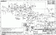
Thanks to Radiomuseum.org, here is the schematic for the reverb driver. I don't think there's a copyright issue since this is from a Philips document.

Signal "t" on the left comes from the OPT and drives the reverb tank (Nachhall-Einheit). "r" at the bottom is the supply to the little amp, coming from the cathodes of the EL84 power amp valves (so probably 12V or so), and "e" is the ground. "s" (top right) is the output which goes via a pot to the preamp.
The OC75 is an old germanium transistor and I'm sure unobtanium, but there must be plenty of PNPs which will do.
Damn I just realised that won't quite work in a guitar amp!
I was reading how that circuit works (I understand about 60% of the German), and it takes the input from the left channel OPT and puts it onto the right channel preamp. This made me realise that if you do it in a (presumably) mono guitar amp, you will either have an oscillator (+ve feedback) or the reverb killing itself (-ve feedback). I'm to lazy to work out which way round. So then you would need a transistor to drive the tank as well.
I was reading how that circuit works (I understand about 60% of the German), and it takes the input from the left channel OPT and puts it onto the right channel preamp. This made me realise that if you do it in a (presumably) mono guitar amp, you will either have an oscillator (+ve feedback) or the reverb killing itself (-ve feedback). I'm to lazy to work out which way round. So then you would need a transistor to drive the tank as well.
Don´t despair.
There´s at least one Guitar amplifier driving the reverb tank from its OT, the mighty Fender Champ 12, reamplifying return signal and reinjecting it backwards into its own preamp.
It works, as long as that closed loop gain is not enough to sustain oscillation.
There´s at least one Guitar amplifier driving the reverb tank from its OT, the mighty Fender Champ 12, reamplifying return signal and reinjecting it backwards into its own preamp.
It works, as long as that closed loop gain is not enough to sustain oscillation.
Attachments
Ah great - thanks JMFahey.
Also, thinking about it more, it's not a direct electrical feedback, so the feedback is at the speed of sound through the springs in the tank rather than almost the speed of light though a wire, so is there any feedback at all?
Also, thinking about it more, it's not a direct electrical feedback, so the feedback is at the speed of sound through the springs in the tank rather than almost the speed of light though a wire, so is there any feedback at all?
Interesting they use a JFET in the recovery circuit, also they peak the recovery coil. I was going to use a 12AX7 see how hissy it is. Maybe add LPF. Its quite interesting not to do an amp for a change! Think I will breadboard first.
But that's how acoustic feedback works e.g. a screeching PA so I'm just going to shut up now before I talk any more crap.
They seem to come in mainly 8R or 600R although I found 150R. I just measured the transformers up. The VTX-121-3015-415 1.5VA mains is good up to about 5KHz at -3dB which is little low. The audio transformer VTX-101-003 is flat as a pancake. I will try the later - the reason for PP LTP is to try and get zero magnetizing current in the core as the audio one is not tolerant to this. Both are about 6.5 to 1 turns with dual primaries and secondaries.
Last edited:
Philips used (mostly?) Gibbs Type 4 reverb tanks with an impedance of (I think) 1475 Ohm (Rdc = 180 Ohm), often combined with loudspeakers of 800 Ohm, both in organ amplifiers and some of their top-of-the-range radios.
In the Philips AG7600 organ amplifier, the drive signal for the reverb tank is taken from the speaker of one of the two channels. The reverb is reproduced through the other channel, so no risk on feedback.
In the Philips B7X44A radio (stereo), which has "reverbeo", it looks like they did the same thing (but I didn't figure out the switching in the schematic yet...).
Attachments
- Home
- Amplifiers
- Tubes / Valves
- Driving reverb tank.