Hey everyone!
Disclaimer: I'm fairly new to diyaudio, amplifiers, power supplies, schematics, PCB design and everything that this forum touches on (read: noob), so I urge you to be patient with me - I am eager to learn though.
That being said - Hi! My name is Mladen 🙂
Anyway, on to the point: Recently I came across @xrk971 thread Hakuin SE Class A HP Amp which got me interested into building my own amp (PCB design and everything).
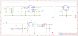
But, since X hasn't opened source his power supply schematic I decided to tackle that on my own (without some extras he implemented). Basically what I tried to do is: Battery Charger --> Boost Converter --> LDO.
Spent last few days reading through data sheets and reference designs and this is what I came up with. I would greatly appreciate if you could fact check the schematic and suggest things I should do (things that I've probably missed).
I plan to use Samsung's EB-BJ710CBE battery (if possible).
Data Sheets:
MCP73871, TPS61178, TPS7A470
Disclaimer: I'm fairly new to diyaudio, amplifiers, power supplies, schematics, PCB design and everything that this forum touches on (read: noob), so I urge you to be patient with me - I am eager to learn though.
That being said - Hi! My name is Mladen 🙂
Anyway, on to the point: Recently I came across @xrk971 thread Hakuin SE Class A HP Amp which got me interested into building my own amp (PCB design and everything).
But, since X hasn't opened source his power supply schematic I decided to tackle that on my own (without some extras he implemented). Basically what I tried to do is: Battery Charger --> Boost Converter --> LDO.
Spent last few days reading through data sheets and reference designs and this is what I came up with. I would greatly appreciate if you could fact check the schematic and suggest things I should do (things that I've probably missed).
I plan to use Samsung's EB-BJ710CBE battery (if possible).
Data Sheets:
MCP73871, TPS61178, TPS7A470
Attachments
Last edited:
Are you just doing this for the experience or are you expecting some practical use out of it as well?
You are aware that you could get about 6 times the battery runtime and a substantially more capable amplifier if you were to expend this kind of effort on an O2 (well, you'd need a split +/-9..12 V supply)? XRK's design isn't bad for what it is, but there's only so much a low complexity single-ended Class A circuit can do in a portable setting. It's pure DIY noveltycore.
SE Class A, while very non-critical in terms of circuit / PCB design skills, is the lowest efficiency circuitry you can get, and as such not normally first choice in anything portable. Your power supply is at the exact opposite end of the spectrum in all respects.
Under which conditions would you bother to engineer a fancy modern fuel system for a car that consumes 25 l / 100 km while going 130 km/h with little more than 4 passengers and their luggage (not an unrealistic stat for the 1930s/40s btw)?
I just find it sad in contrast to having a tiny MP3 player that'll get 10 hours out of a 200 mAh pouch cell while having a half-decent headphone driver built-in - state of the art in 2009.
Anyway, I don't see any high-frequency (R)LC filtering after your boost converter (you may want to research how much PSRR your LDO has in the 100s of kHz - quite possibly not much at all). Also, some common-mode choke action at the input and output would be a good idea.
Last edited:
Hey @sgrossklass
First - thanks for the input! 🙂
Second - this one is for the experience, I think - and learning stuff. Eventually I plan on building something - I haven't been this excited about something in a while - there's joy in building things yourself. I will definitely check the O2 - thanks for the recommendation!
Beside (R)LC filtering and common-mode choke you don't see any other mistakes I've made? Battery charger is what I'm interested the most in - have I done that part of the schematic right? USB-C connection looks good?
Thanks again!
Hi @MladenGavric
Speaking about switching regulators (used in audio projects), it is almost impossible to make it right from the first try. So I would suggest you to build and measure/test it first, then you will be able to learn a lot from inherent mistakes.
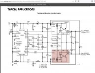
I almost finished to design a PSU prototype, also for a portable (or not) headphones amp. It is based on a schematic from LT3094 datasheet. I have never tried switching regulators in my audio projects, so this will be the first time. 🙂
Speaking about switching regulators (used in audio projects), it is almost impossible to make it right from the first try. So I would suggest you to build and measure/test it first, then you will be able to learn a lot from inherent mistakes.
I almost finished to design a PSU prototype, also for a portable (or not) headphones amp. It is based on a schematic from LT3094 datasheet. I have never tried switching regulators in my audio projects, so this will be the first time. 🙂
Attachments
It is no problem using SMPS in audio.
You just have to do it right.
See for example Jan Didden's silent switcher.
Linear Audio Silent Switcher V3 – diyAudio Store
I have used LTC3265 which is very simple to use.
It does have its limitations in voltage and current.
And the OPA1622 has good PSRR.
New Audio Op Amp - OPA1622
Are you sure you want to DIY with DFN 7x5 (the only available package of the LT8582) ?
Cheers,
Patrick
3094 is the new one for AD, if I'm not mistaken, right?
Yes, it is newer, as LT3045-1 is. Their VIOC feature seems interesting to me. LT3045 (without -1) and LT3042 don't have it.
"The VIOC pin is used to control an upstream switching converter and facilitate a design solution that maximizes system efficiency while providing good transient response, low noise, and high power supply ripple rejection (PSRR) by maintaining a constant voltage across the LT3094 regardless of the device’s output voltage."
Are you sure you want to DIY with DFN 7x5 (the only available package of the LT8582) ?
It is easier for me to solder DFN chips, like ESS9038Q2M, using hot air, than TSSOP chips, like PCM1794. For a little extra control, I always design the DFN chips footprint having 0.5 mm longer (than chip case) pads for every pin.
I made something similar for the PCA a couple years back too.
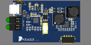
I think you are missing a protection chip, but I'm not an engineer and almost certainly know less than you. This is what I sent to fab IIRC. I don't recall if it worked, since I moved away from the idea shortly after - I think it might have but the MCP73871 was getting way too hot.
Also it's possible the design might have been missing proper load sharing apparatus but I don't remember for sure.


Soldering the MCP73871 by hand wasn't an issue with extended pads as the other poster suggested, but the comically miniature BQ297 and the FET (I don't think the FET in the schematic is the one I used, Arrow's order history seems to be broken so I can't look it up right now) were a huge pain. I don't recall offhand if the DW01 is compatible with the design but I would explore something larger than WDFN2x2 if not using oven/air.
I think you are missing a protection chip, but I'm not an engineer and almost certainly know less than you. This is what I sent to fab IIRC. I don't recall if it worked, since I moved away from the idea shortly after - I think it might have but the MCP73871 was getting way too hot.
Also it's possible the design might have been missing proper load sharing apparatus but I don't remember for sure.
Soldering the MCP73871 by hand wasn't an issue with extended pads as the other poster suggested, but the comically miniature BQ297 and the FET (I don't think the FET in the schematic is the one I used, Arrow's order history seems to be broken so I can't look it up right now) were a huge pain. I don't recall offhand if the DW01 is compatible with the design but I would explore something larger than WDFN2x2 if not using oven/air.
Last edited by a moderator:
I've learnt a bit more since the time I posted the above question and went a bit different path as suggested by @sgrossklass
This is what I came up with since than:
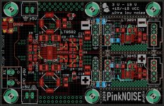
BQ25616JRTWR 5V Battery Charger IC (/w external protection) --> ADP5071ACPZ-R7 ±10V Split-Rail Boost Converter --> ADP7142AUJZ-5.0-R7 +9V LDO for Positive Rail and ADP7182ACPZN-R7 -9V LDO for Negative Rail
This is what I came up with since than:
BQ25616JRTWR 5V Battery Charger IC (/w external protection) --> ADP5071ACPZ-R7 ±10V Split-Rail Boost Converter --> ADP7142AUJZ-5.0-R7 +9V LDO for Positive Rail and ADP7182ACPZN-R7 -9V LDO for Negative Rail
Attachments
- Home
- Amplifiers
- Power Supplies
- Portable Headphone Amp Power Supply 18V