Hello all
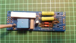
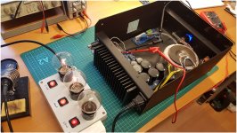
I was handed down a pair of EC AW-PRO 1 monoblocks from a friend. He stated there was some problem with powering them on. The plan was to service them with new caps, and finding the power-on issue. After some dismantling and inspection there clearly has been a few hotspots in them. They are remarkably similar in the burnmarks in both amps, so I'm thinking there is something fishy going on. I was given some vague info about the slowstart boards beeing retrofitted, and the soldering of mains wire on and around the board is clear evidence of such.
I have no prior experience with the brand and struggle to find any usefull documentation or schematics, other than the amp board. Absolutely none on the slowstart and PSU/sisterboard
I guess what I'm asking is if there is something obvious to start with i regards to finding out why these boards are so burnt?
Attachments
Last edited:
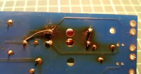
Looks due to inadequate derating. There was a failure at some point, burning some pcb traces.
I'd remove the parts, clean the board, and replace all the parts on that board, as well as the trim pot
and resistor on the other board. Raise the power resistors above the board by about their diameter,
and use the highest power resistors that will fit properly.
I'd remove the parts, clean the board, and replace all the parts on that board, as well as the trim pot
and resistor on the other board. Raise the power resistors above the board by about their diameter,
and use the highest power resistors that will fit properly.
Last edited:
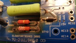
The failure might have been R207 on the slowstart board, where burnmarks are most prominent. R207 is dead
Possibly, or else something downstream. The entire amp should be checked out carefully,
since it is pretty old.
since it is pretty old.
Last edited:
I'd troubleshoot the amp itself before bothering with the slow start board. Use a 100w incandescent or halogen bulb as a current limiter, and the soft start can be bypassed
Bring up an old amp like this slowly on a Variac. Let it cook for an hour or two at half line, and
then slowly increase to nominal. Watch for overvoltage on the main capacitors, since current
line voltages can be significantly higher than they were 20 years ago.
then slowly increase to nominal. Watch for overvoltage on the main capacitors, since current
line voltages can be significantly higher than they were 20 years ago.
I don't have a variac but I do have a 3-step bulb limiter with 30, 40 and 60W bulbs. I could do voltage checks on main voltages VCC and VDD for starters
Yes, but only after the bulb power up works ok. Then remove the bulb for further testing,
as the bulb can still drop some AC line voltage even with a good amp.
Bear in mind that a bulb tester does not give the amp a soft start, instead it only drops the
input voltage down in the event of excessive current draw. The power supply capacitors could
need some reforming time after such a long time being unused. Check the ripple voltage across
each one.
Last edited:
Plenty of true EC experts here, so I will wait and see.
However, you are in Norge, why don't you give the company a call ?
However, you are in Norge, why don't you give the company a call ?
I'll start off by doing that. I have to look into making a simple filter for my meter, as I don't have a scope to measure ripple
Yes, but only after the bulb power up works ok. Then remove the bulb for further testing,
as the bulb can still drop some AC line voltage even with a good amp.
Bear in mind that a bulb tester does not give the amp a soft start, instead it only drops the
input voltage down in the event of excessive current draw. The power supply capacitors could
need some reforming time after such a long time being unused. Check the ripple voltage across
each one.
It gives enough of a soft start to cover what the soft start circuit in the amp is doing - avoiding inrush current of a toroidal transformer from tripping the breaker.
Depending on your meter you can just measure AC on the DC.
Use a large coupling cap to your meter if you're not sure it has one built-in.
Jan
Use a large coupling cap to your meter if you're not sure it has one built-in.
Jan
Both my meters are rather cheap, not true RMS or super accurate, so using a cap is probably a good idea.
I did a test on one of the amps and bypassed the slowstart, powered it on with aprox. 320mA limit and it has been sitting on the bench for a few hours now. Powered up with no hassle, protection relay came off and all seems quite stable
I also contacted manufacturer directly and kindly asked for schematics, but understandably they will not release that to the public. They asked for pictures and more info though, so maybe I will get some pointers. Incredible swift response from them I must say!
Attachments
Did some desoldering on PSU board to better manually trace R508. Turns out this is just adjustment for the blue power LED on the front panel. Consists of four blue LED's so maybe someone wanted a brighter blue glow and turned them up too high - I don't know, but seems totally unrelated to the slowstart
With such inquiries you usually get this reply resp. statement:Plenty of true EC experts here, so I will wait and see.
However, you are in Norge, why don't you give the company a call ?
We strongly recommend that you send the device to us, even if you are an electronics technician yourself. Since we developed the devices, we know best what to do.
For me it is always an indirect admission that it is a bad and unreliable circuit design like this one under
Electrocompaniet Ampliwire 100 (AW 100 AW100) different Versions
Electrocompaniet AW-100 troubleshooting (right channel intermittent soft popping)
Electrocompaniet Ampliwire 100
as well as no existing well-executed circuit diagrams and service manuals.
For giving more exact advice concerning the burned parts and possible design errors a schematic diagram of the inrush current limiter would be helpful. It is maybe this amp in post #53 under
Psychonaut's lille "hifi"... NY PRE-AMP;=) | Side 2 | Hifisentralen
Then there are easy circuits for create an own schematic.
I strongly advise against buying old and new devices of this brand from Elektrocompaniet in general, because I know many users who have issues with them and could only take a long time to fix them (reverse engineering).
Last edited:
General knowledge should suffice to decipher this glaringly commonplace circuit. I would think twice to pay 1 Norwegian krone for this amplifier. The omission of output stage emitter resistors exceeds the acceptable level for professional incompetence.
With such inquiries you usually get this reply resp. statement:
We strongly recommend that you send the device to us, even if you are an electronics technician yourself. Since we developed the devices, we know best what to do.
For me it is always an indirect admission that it is a bad and unreliable circuit design like this one under
Electrocompaniet Ampliwire 100 (AW 100 AW100) different Versions
Electrocompaniet AW-100 troubleshooting (right channel intermittent soft popping)
Electrocompaniet Ampliwire 100
as well as no existing well-executed circuit diagrams and service manuals.
For giving more exact advice concerning the burned parts and possible design errors a schematic diagram of the inrush current limiter would be helpful. It is maybe this amp in post #53 under
Psychonaut's lille "hifi"... NY PRE-AMP;=) | Side 2 | Hifisentralen
Then there are easy circuits for create an own schematic.
I strongly advise against buying old and new devices of this brand from Elektrocompaniet in general, because I know many users who have issues with them and could only take a long time to fix them (reverse engineering).
Thanks for the link, those amps are identical indeed. Funny to see the inside of another one with the exact same burnmarks....
Just to clearify, as I gather there is not much love for this brand, I did not pay anything for these amps.... I got them just because they are not working and thought it would be nice to fix and use them.
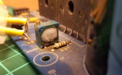
Did some more testing. Replaced the dead resistor on slowstart board and cleaned up and resoldered a bit. Testet with limiter to be safe. Inrush circuit relay pulses like crazy and does not stabilize. Changed the 33uF cap with the what I had on hand and now it works fine. Anyhow, those resistors get stupid hot after just one minute so it will obviously not last.
Drew up a schematic for the inrush circuit. Looks overly simple to me, but I lack the knowledge to calculate if there is something faulty in the design
Drew up a schematic for the inrush circuit. Looks overly simple to me, but I lack the knowledge to calculate if there is something faulty in the design
Attachments

Gentlemen, and Tief in particular, please stay calm.
The EC company and their amps are traditional or even
vintage in the meantime, and thousands have been sold
to many satisfied customers.
Generally I would call these "easy" to repair, but of course
it is not intended that "common" people do this who would
call somebody else for changing a car tire (.. buy a scope).
This said - it is not one of the most reliable products, but
more than "good enough" for the purpose.
For a manufacturer it is good advice to keep the repairs
in their own workshop or rely on serious distributors only.
As a manufacturer you can not know what will happen in
ten or twenty years most of the time. Whoever is sure he
can - stand up please and earn a lot of money (pm me).
Amps of this particular origin are descendants of the work
of Otala / Leinonen and are generally pretty similar to each
other in decades. This alone is interesting for many people.
For the OPs amp - you probably do not need a soft start
circuit if your home electricity can handle inrush currents.
However a start up current limiter is a good way to protect
other parts of the amp during switch on, but this one was
probably running too hot.
N101N : not sure about the "omission of output stage emitter
resistors" at the moment, but with "ring emitter" devices of
the time (Fujitsu, Toshiba and later Sanken) it was commonplace
and my company sold a four digit number using this technology -
no emitter resistors.
I will not explain here why emitter resistors could be omitted in
this case. Read the manuals.
Post 19 : this is the usual way to do a simple limiter, but it can be
done better of course. I you engage the relay "on its own" or with
use of the secondary dc voltage is is working also as intended. The
excessive drop on the two resistors can be avoided this way. Check
the cap also (we used 47uF in this place).
- Home
- Amplifiers
- Solid State
- Seeking Electrocompaniet knowledge, or maybe just general knowledge