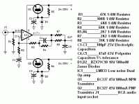
Hello
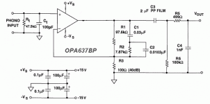
Since the gain of this preamp (like any phono preamps) go down to 0 db over 100 khz, and most decompensated op amp are stable in gains equal to or greater than five. In the phono preamp like the one in the image, does using a OPA637 or any decompensated op amp can made the circuit oscillate at arround 100 khz ?
Thank
Bye
Gaetan
Attachments
No. It may oscillate, but at a much higher frequency, somewhere around the frequency where the loop gain falls to 0 dB.
With a slew rate >40 v/usec, I'd say OPA637 is a definite oscillation candidate.
I'd bypass R1 with a 33 pf disk cap, unless C1 & c2 are also both ceramic disk caps. You should also put .01 to .1 uf disk caps across the power supplies within 1" of the package.
I'd bypass R1 with a 33 pf disk cap, unless C1 & c2 are also both ceramic disk caps. You should also put .01 to .1 uf disk caps across the power supplies within 1" of the package.
But even then you are using an op-amp meant for a gain of at least five with full feedback, so chances are it will oscillate.
If you haven't bought the resistors and capacitors yet, you could redesign the circuit for a minimum gain of five and increase C4.
I'm not sure if this answers the question, but the input signal rate of change that you need to drive the op-amp into slew rate limiting would be pretty much the same as with an OPA627 and unity high-frequency gain of the RIAA amplifier.
Hello
Here's the opamps that I have in my part bin. Most of them will need good .1 uf caps across the power supplies pins and the caps need to be very close to those pins. I would use 15 volt for the supply.
LM4562
LM6172
OPA627
OPA637
NE5532
AD825
LME49720
The soundstage of the OPA627 are very wide and I like that.
Thank
Bye
Gaetan
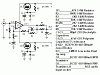
The circuit from post 10 should work with an OPA637 and well-decoupled +/- 15 V supplies. (I'm not sure if it will work with an OPA637 and the emitter-followers-with-no-output-decoupling supplies shown on the schematic.)
Hello
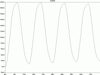
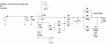
I did simulated with Ltspice, the circuit from post 10 with an inverse-riaa at the output, wen taken at the output after the inverse-riaa, thd are low but the slew rate look bad, I include the .asc file, and images. I use OP37 in the simulation because that opamp are in Ltspice.
Any reasons why the slew rate look bad ?
Any suggestions ?
Thank
Bye
Gaetan
Attachments
Last edited:
You need to swap the inverse RIAA network from the circuitry's output to it's input.
Best regards!
Best regards!
With a slew rate >40 v/usec, I'd say OPA637 is a definite oscillation candidate.
I'd bypass R1 with a 33 pf disk cap, unless C1 & c2 are also both ceramic disk caps. You should also put .01 to .1 uf disk caps across the power supplies within 1" of the package.
Adding a cap across R1 can actually make things worse, the OPA637 is not unity gain stable, and a cap across R1 will give a gain of one at higher frequencies.
Gaetan, I have a passive-active 2-stage phono board that I can send you (no charge) for evaluation. I would like to ask you to post the result here after your analyses and test.Hello
I did simulated with Ltspice, the circuit from post 10 with an inverse-riaa at the output, wen taken at the output after the inverse-riaa, thd are low but the slew rate look bad, I include the .asc file, and images. I use OP37 in the simulation because that opamp are in Ltspice.
Any reasons why the slew rate look bad ?
Any suggestions ?
Thank
Bye
Gaetan
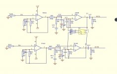
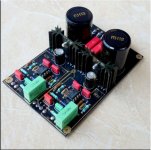

If interested, PM your mailing address.
If you want to keep the board after testing, paypal me whatever you think it is worth as compensation. I will send the board with Chinese 5532. You can retest with LME49720 to see the improvement in noise.
If you just want to keep it, that's fine too.
With a high-frequency gain of 77.8 and 200 mV peak input signal, the op-amp is hard clipping.
Hello
Your right, I was using that slew rate test for power amp simulations I forgot to reajust it for phono preamp test, so I've just reduce the peak input signal to 10 mv.
Thank
Bye
Gaetan
You need to swap the inverse RIAA network from the circuitry's output to it's input.
Best regards!
Hello
I've try that and it's make thing worse.
Thank
Bye
Gaetan
Gaetan, I have a passive-active 2-stage phono board that I can send you (no charge) for evaluation. I would like to ask you to post the result here after your analyses and test.
View attachment 862855 View attachment 862856 View attachment 862857
If interested, PM your mailing address.
If you want to keep the board after testing, paypal me whatever you think it is worth as compensation. I will send the board with Chinese 5532. You can retest with LME49720 to see the improvement in noise.
If you just want to keep it, that's fine too.
Hello
Thank for that nice offer. But for a long time I can only do circuit simulations, I have to repair my turntable and completely remake my power amp, and I have to do heavy repairs in my house basement.
So, I have to pass for your offer.
Thank
Bye
Gaetan
Last edited:
- Home
- Source & Line
- Analogue Source
- About a phono preamp and decompensated op amp
