Hello,
NEWBIE on board😉
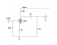
I'm building a simple 1 tube preamp based on 5670 tube (see the attached drawing) and would appreciate any suggestion for getting the best out of it.
with any lower cathode resistor than 2K I'm getting distorted output.
Any suggestion from experienced members will be appreciated.
Thanks
NEWBIE on board😉
I'm building a simple 1 tube preamp based on 5670 tube (see the attached drawing) and would appreciate any suggestion for getting the best out of it.
with any lower cathode resistor than 2K I'm getting distorted output.
Any suggestion from experienced members will be appreciated.
Thanks
Attachments
That cathode resistor is much to big.
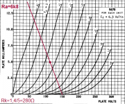
With 5mA the tube needs Vg=-1,4V , gives Rk = 1,4/0,005 = 280Ω
Take 270Ω
Thanks but I’ve done this calculations before and tried 250 Ω and discovered that any value below 2kΩ gives distorted sound.
Any idea why?
Last edited:
Another question, I would like to add a volume pot, should I put it at the input or the output?
100KΩ or 50KΩ ?
Thanks
100KΩ or 50KΩ ?
Thanks
You might be overloading it with the input signal. Higher cathode resistor value allows for more input, but at the same time the linearity will be much worse.Thanks but I’ve done this calculations before and tried 250 Ω and discovered that any value below 2kΩ gives distorted sound.
Any idea why?
But anyways you're using the tube far outside its linear region, 150V B+ and 6.8k load are both too low.
Both will work. And the input cap isn't really neccessary.Another question, I would like to add a volume pot, should I put it at the input or the output?
100KΩ or 50KΩ ?
You might be overloading it with the input signal. Higher cathode resistor value allows for more input, but at the same time the linearity will be much worse.
The source is a DAC output.
But anyways you're using the tube far outside its linear region, 150V B+ and 6.8k load are both too low.
According to the tube data sheet 150Vdc is okay, correct me if I'm wrong. considering that at the moment 150Vdc is what I can provide what Anode resistor should I use? (tried 10K with the same results).
Thanks
Attachments

Last edited:
Doesn't really say anything.The source is a DAC output.
If it has typical commercial 2Vrms (2.83V peak) output, it will indeed overload the stage with 1.5-2V bias.
That's the plate voltage, not the PSU voltage.According to the tube data sheet 150Vdc is okay, correct me if I'm wrong.
I would strongly suggest finding a way to provide higher voltage (there are voltage doublers and stuff) or using another tube that is more happy working with lowish voltages (6922 or something).considering that at the moment 150Vdc is what I can provide what Anode resistor should I use? (tried 10K with the same results).
If it is impossible, then I'd probably go for something like 18-22k with 510-750 Ohm cathode resistor respectively.
And if you have 2Vrms input indeed, you'll need to drop it by half - you can use, say, 50k volume potentiometer plus the 47-51k series constant resistor before it.
This is a VHF capable triode, and you have no grid-stopper...
Are you reffering to a series resistor with the input?
Are you reffering to a series resistor with the input?
Yes.
Also, with this design your output impedance will be rather high. It's not the end of the world, but I would look into using a 12b4a tube with a CCS. That way you can still using a single cathode bias resistor, but you won't be raising your output impedance by a large amount.
Plate impedance in the datasheet does not mean use a plate loading resistor equal to that value. The common suggestion is that if your plate loading resistor needs to be at least 3x plate impedance to get reasonable audio performance.
Output impedance will be way too high to be useful as a preamp. Adding a second tube or adding a pair of mosfets to buffer the output can solve this issue.
Output impedance will be way too high to be useful as a preamp. Adding a second tube or adding a pair of mosfets to buffer the output can solve this issue.
Thank you all..
I have a non directly related question, I've found a transformer with an output of 250Vac but after a bridge rectifier and smoothing capacitors I'm getting a 330Vdc reading, how is it possible?
I have a non directly related question, I've found a transformer with an output of 250Vac but after a bridge rectifier and smoothing capacitors I'm getting a 330Vdc reading, how is it possible?
Output impedance will be way too high to be useful as a preamp. Adding a second tube or adding a pair of mosfets to buffer the output can solve this issue.
Any suggestions for a 5670 tube based schematics?
Thanks
250V AC is an RMS rating. The peak voltage is higher. I'd say close to 330V 😉
If I understand you correctly I'll have to use a high wattage resistor to lower the 330Vdc to an acceptable 250Vdc level for the 5670 tube as it's absolute maximum rating is 330V.
If I understand you correctly I'll have to use a high wattage resistor to lower the 330Vdc to an acceptable 250Vdc level for the 5670 tube as it's absolute maximum rating is 330V.
No. The maximum plate voltage is the voltage across the tube with no signal.
Your plate resistor will drop a considerable amount of voltage, so you need to measure the voltage at the plate of the tube and subtract it from your cathode voltage. If the number is less than 250 with no signal, then you are fine. If it is above that, then yes you would need to find a way to lower your plate voltage.
For what its worth, if you can't use any other tube, I would try some local negative feedback.
It would reduce your gain and output impedance
The Valve Wizard
It would reduce your gain and output impedance
The Valve Wizard
Thank you all..
I have a non directly related question, I've found a transformer with an output of 250Vac but after a bridge rectifier and smoothing capacitors I'm getting a 330Vdc reading, how is it possible?
If you use full wave, bridge rectification you will get 1.414*VAC 120Hz, if you use half wave rectification you will get .707*VAC 60Hz
If I understand you correctly I'll have to use a high wattage resistor to lower the 330Vdc to an acceptable 250Vdc level for the 5670 tube as it's absolute maximum rating is 330V.
No, your transformer is producing absolutely the correct voltage for a nice cathode follower output section of a tube pre.
Forget about this5670 tube for high- freq. Use a nice and available audio double triode like 12AU7 or 12AT7 and build a well known two stage line amp like every other good tube audio designer did. That provides you with a low output impedance that you need and it will fit well into using your transformer.
The resulting distortions may occur because of impedance matching problems with this poorly designed circuit you show in the first post.
Try to understand how to design a good tube amp stage by reading books first.
Without ANY theoretical knowledge nobody has ever build a real working audio tube amp. And you won't do either.
So first get the basic knowledge by self studying. Then build a circuit and ask when questions occur. Not the reverse way. It won't work out.
Last edited:
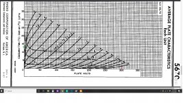
So, we'll assume you have 300V of B+ and call the Rp of the 5670 about 7K. We'll put a red dot on the curves for the 300V. If we load the tube at about 3x Rp, we'll call that a 22k resistor. The maximum amount of current that can be drawn through a 22K resistor from a 300V supply is (based on Ohm's Law) 300V=I*22000 which is 13.6mA. We will put a green dot at 13.6mA on the vertical axis.
Attachments
- Home
- Amplifiers
- Tubes / Valves
- Simple 5670 tube based line stage design help