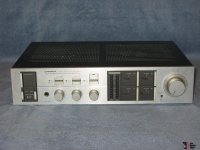
Resistor Getting Super HOT with some SMOKE! HELP PLEASE!
So i just changed the fuse 3.15 amp to my amp and since then the front lights are very dimmed (seems like low in voltage) and the big white resister (R-592 (right channel, please see the attachments, there are 2 big white colored resistors for each channel) is getting super hot and i can see some white smoke coming from the resistor and had to turn off within 1 or 2 seconds before it blows up or cause other damage.
It's not even clicking (the speaker protection relay), coffeehouse there is something wrong with some component. what seems to be the problem ? Some expert help please.
Attachments


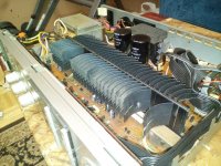
Reads like you have shorted output transistor(s), the white resistors being the emitter resistors. Will take a look at the sm so time for an expert to chime in. All this from only changing a fuse? Was unit working ok before? Did it suddenly go silent? Little more history required...
Do you have a multimeter, are you able to diode test the output transistors (amp powered off/unplugged...)
Hey mbz, which output transistors? or it could be a faulty transistor maybe? or more then ones? yes i do have a digital multi-meter, can you please guide me. i'll do the test with power off as advised.
and here's the picture below of the resistor which gets hot like lava and makes smoke as soon as i turn on for 1 or 2 seconds ...

and here's the picture below of the resistor which gets hot like lava and makes smoke as soon as i turn on for 1 or 2 seconds ...
Last edited:
*************************************
Link for the service manual : Pioneer SA-1040
*************************************
PIONEER SA-1040 SERVICE MANUAL Pdf Download | ManualsLib
Link for the service manual : Pioneer SA-1040
*************************************
PIONEER SA-1040 SERVICE MANUAL Pdf Download | ManualsLib
Last edited:
Most likely you've got a failed output transistor with a short between c-e.
With amp powered off/unplugged measure the resistance between the case of an output transistor and any leg of the nearby emitter resistor. Repeat for next transistor. When testing the other channel/outputs, you will need to measure against the corresponding emitter resistor. Don't expect a near short.
With amp powered off/unplugged measure the resistance between the case of an output transistor and any leg of the nearby emitter resistor. Repeat for next transistor. When testing the other channel/outputs, you will need to measure against the corresponding emitter resistor. Don't expect a near short.
I should add that output transistors rarely fail solo. Expect other damage eg, driver transistors... Ooops, You should test output transistors on the side with the hot emitter resistor...ie, the right channel
Last edited:
so i see 14 transistors and 4 diodes (i guess voltage regulators) under the heat sink ... do you want me to go all of them? and which other transistor you want me to test which is located beside that big white resistor ? can you give me the ref number from the diagram please.
wanting you to resistance check the output transistors on the right channel, ie, one probe on the metal case, the other on any leg of the emitter resistor for that channel, give me 2 min and I will references...
Wanting to measure resistance between Q532 Collector and any leg of R592.
Repeat for Q526 collector and R592. The metal flange/base of the transistor is also the collector so it's a easy measurement point.
Repeat for Q526 collector and R592. The metal flange/base of the transistor is also the collector so it's a easy measurement point.
Wanting to measure resistance between Q532 Collector and any leg of R592.
on 200 ohms settings on the meter and connected the node with transistor's collector, the value shows up as 00.3 on first leg, 00.6 and second leg and 00.9 on third leg of the resistor.
Repeat for Q526 collector and R592.
on 200 ohms settings on the meter and connected the node with transistor's collector, the value shows up as 00.3 on first leg, 00.7 and second leg and 00.9 on third leg of the resistor.
If i set the multi-meter on diode setting then all the values shows up as zeros with a beep sound.
Last edited:
Results suggests Q532 and Q526 have failed (c-e) short. If you have any doubt about the test then you can redo but measure from the middle leg of the transistor to R592...
Next step is to check for other damage.
R592 looks ok.
Diode test Q528, 530, 522 and 524
Also Q602, 604, 614, 616
Diode test D602, 604
Resistance test R588, 590, 586
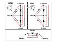
Refer to previous graphic on diode testing, all tests with amp powered off/unplugged.
Visual check "all" components in the area for signs of stress, eg, discoloured/charred resistors...
Next step is to check for other damage.
R592 looks ok.
Diode test Q528, 530, 522 and 524
Also Q602, 604, 614, 616
Diode test D602, 604
Resistance test R588, 590, 586
Refer to previous graphic on diode testing, all tests with amp powered off/unplugged.
Visual check "all" components in the area for signs of stress, eg, discoloured/charred resistors...
Before doing anything else in order not to make more damage build a bulb limiting device. 100W filament bulb in series with the amp.
^^^^ Agree, a Dim Bulb Tester will be required at first power up after parts replacement.
Google for plans...
Google for plans...
- Home
- Amplifiers
- Solid State
- Pioneer SA-1040 Amplifier : RESISTOR (R592 - .33X2/5W) Making Smoke and getting super