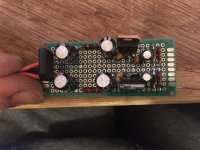
I have built Rod Elliot’s simple preamp supply with bits I had on hand. I will eventually be building an active crossover for the home system and am having a go at the basic building blocks for experience.
I have followed the schematic on figure 2. on his wonderful page: Power Supply for Preamps except I didn’t have 100nf ceramic capacitors and so used 1F ceramics.
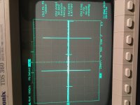
With 2.2k resistors across the outputs world as to draw a ~5mA constant current and discharge the caps when off, I probed across the 10uf output capacitor (with a ground spring on the probe) and got much more noise than I was expecting.
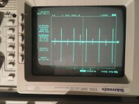
The frequency of the spikes in the photo are at almost exactly 100Hz but I am baffled as to what might cause them, I was expecting much better noise performance?
Is the bridge rectifier?
I have followed the schematic on figure 2. on his wonderful page: Power Supply for Preamps except I didn’t have 100nf ceramic capacitors and so used 1F ceramics.
With 2.2k resistors across the outputs world as to draw a ~5mA constant current and discharge the caps when off, I probed across the 10uf output capacitor (with a ground spring on the probe) and got much more noise than I was expecting.
The frequency of the spikes in the photo are at almost exactly 100Hz but I am baffled as to what might cause them, I was expecting much better noise performance?
Is the bridge rectifier?
Attachments

Last edited:
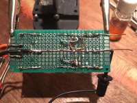
These are charging pulses of current into the first capacitors, from IR voltage drop due to layout.
The connection between the secondary center tap and the two 4700uF capacitors should not be shared
with the rest of the circuit. The ground connection between the 4700uF capacitors and the regulators
must be separate, taken directly from the input capacitors (near their bodies) to the regulator ground pins.
The second 4700uF capacitors should return directly to the regulator ground pins, and then a single wire
from there goes back to the input capacitors' ground point.
Last edited:
I see, so I have in effect created a pair of miniature ground loops or is that charging the first set of filter caps causes a change in the ground potential of the regulators which then oscillate whilst every thing settles?
Thank you for you help by the way.
Thank you for you help by the way.
Yes, it's hard to see details on the breadboard, probably not oscillation per se, maybe some ringing,
but you could post a clearer waveform, with an expanded time base. Unless your probe is picking up spikes,
some will. Try moving the probe physically farther away from the input side.
The ideal way is two separate secondaries, each FWB rectified, filtered, and regulated, and each only connected
to circuit ground at the output terminals, with the rest of the circuit floating. This does not apply to a center tapped winding, though. The common ground, like for audio circuits, can have problems.
Last edited:
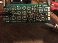
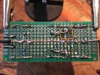
Ok, apologies. I hope this photo is clearer. 🙂
I have desoldered the second set of 2200uf capacitors (after the resistors on the rectifier as well as the side) as well as the 1uF ceramic caps.
If I have understood you correctly, I will solder the negative of one 2200uF capacitor to the ground of the 7812, the positive of the other 2200uf cap to the ground of the 7912 and then a separate ground wire from each going back to the junction of the CT wire and the two primary 2200uF caps?
Attachments

In this circuit use just one ground wire connection, or else another ground loop will be introduced.
Also try moving the transformer secondary center tap wire connection farther to the left.
Also try moving the transformer secondary center tap wire connection farther to the left.
Last edited:
I'm sorry I don't follow what you mean by saying "only one ground connection"? As in making sure the RCA shields are insulated from the chassis for example?
Is the scheme with the proposed modifications reasonable?
Is the scheme with the proposed modifications reasonable?
Is the scheme with the proposed modifications reasonable?
I'll try to post a sketch soon, but my program is acting up right now.
I could be wrong but those caps dont look big enough for 2,200uF 25V
The main thing with a power supply pcb is to have the flow from one end to the other.
The charging impulses into the smoothing caps must be kept away from the output.
So into rectifiers into smoothing caps into regulator to output.
The last time I saw switching spikes like those was on a high voltage valve amp !
Usually low voltage supplies dont suffer from switching spikes, or at least I havent seen it.
I could be wrong but those caps dont look big enough for 2,200uF 25V
The main thing with a power supply pcb is to have the flow from one end to the other.
The charging impulses into the smoothing caps must be kept away from the output.
So into rectifiers into smoothing caps into regulator to output.
The last time I saw switching spikes like those was on a high voltage valve amp !
Usually low voltage supplies dont suffer from switching spikes, or at least I havent seen it.
Well spotted, the caps are actually 470 uF 25V new capacitors, I had originally built it with 2200uF caps from my bits box and changed them in case the they were buggered. I have some 2200uf caps on order, which should be here in a day or two.
Would capacitor size make a difference?
It may be me, I am not an expert on using an oscilloscope, I read to use a ground spring (rather than the clip and wire) and to probe directly on the out put caps, is there some trick to it?
I'll try to post a sketch soon, but my program is acting up right now.
Thanks for your help Ray. 🙂
Yes, and move el. capacitors close to each other (+ to -).Also try moving the transformer secondary center tap wire connection farther to the left.
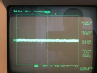
Measure the voltage across D7 and D8 with scope ground on output zero volt line.
With the scope set for 2mV per division, 5ms sweep and glitch detect on?
If so I get this:
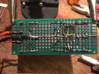
(Changed topography to ground second set of capacitors directly to regulator pins)
Cheers Nigel. 🙂
Attachments
Last edited:
Yes, and move el. capacitors close to each other (+ to -).
thanks Vovk, the proper caps for the regulator will be bigger and fit fairly tighly in the space, these are just for testing purposes.
What exactly does the part about moving the connection further to the left mean? If I extend it with a wire... isn't that the same as extending it with a wire? 😕
Sorry about the basic questions chaps and thanks for all your help.
All the current pulses go through that wire. It's very critical for where it is to be connected.
Last edited:
Thank you very much chaps, by removing the CT wire From overlapping the primary capacitor wire and circuit earth track and resoldering it so it just abutts the junction where they meet (I.e. further left as everyone said 😀) and the result was magic, the spikes disappeared straight away.
Thanks again for taking the time to help me out.
Thanks again for taking the time to help me out.
Attachments
In those situations, think as you are the electrons inside the wire. Do you prefer a long way from job to house, as an example? Or do you prefer a short one? As inductances are acting as reactive elements, their "ways" are like you turn 90° at the corner in a direction apart from you way. So, again, do you prefer few turns at the corners or fewer ones?
- Home
- Amplifiers
- Power Supplies
- What is going on with my linear power supply?