I have another one I need help with, I think these are class AB and I've never worked on anything but class D before.
I received this amp with a blown power supply and a shorted output. Thus far I have replaced the PS FETs, gate resistors (originals were in tolerance but scorched) and all 4 outputs. All with original parts.
The amp currently works BUT:
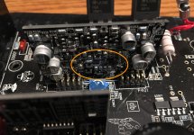
At idle, one bank of outputs gets hot while the other stays cold and part of the driver card gets hot (pictured below.) The passive components between the driver card and outputs seem to be ok.
I have not yet touched the bias pot. Since it's only one bank of outputs getting hot I assumed there's more work to do. I could be completely though, I don't know what normal behavior for these amplifiers is.
Any advice on how to proceed is greatly appreciated.
I received this amp with a blown power supply and a shorted output. Thus far I have replaced the PS FETs, gate resistors (originals were in tolerance but scorched) and all 4 outputs. All with original parts.
The amp currently works BUT:
At idle, one bank of outputs gets hot while the other stays cold and part of the driver card gets hot (pictured below.) The passive components between the driver card and outputs seem to be ok.
I have not yet touched the bias pot. Since it's only one bank of outputs getting hot I assumed there's more work to do. I could be completely though, I don't know what normal behavior for these amplifiers is.
Any advice on how to proceed is greatly appreciated.
Attachments

How much current is it drawing?
What is 'hot' and how long does it take to get there?
Does it produce clean audio?
Whenever repairing a class AB amp where outputs have to be replaced, start with the bias fully down (CCW in this amp).
What is 'hot' and how long does it take to get there?
Does it produce clean audio?
Whenever repairing a class AB amp where outputs have to be replaced, start with the bias fully down (CCW in this amp).
1.9 amps @ 12.5 volts at idle once rail voltages have been established.
I apologize, I shouldn't have used subjective terms. I will get my thermocouple out of storage and provide numerical values.
In the interim, the bank in question takes about a minute at idle to make that section of the heatsink noticeably warmer than anywhere else. All testing is being done clamped to the heatsink.
The driver card becomes warm boarding on uncomfortable to touch after about 2 minutes but doesn't seem to be getting any warmer.
I will carefully clear the blue glue from the bias pot and set it as you instructed.
I missed a question
Yes, it does produce clean audio according to my ear. I need to burn a cd with a test tone and check it on the scope.
Edit:
With the bias pot at full CCW, idle current is 0.93 @ 12.5 volts and both banks of outputs appear to be staying cool.
The driver card is heating up as before.
The PS FETs are slightly warm, they were staying cool previously. (This probably doesn't matter, I'm just sharing all my observations.)
Last edited:

It looks borderline. In the future, align the trace ground with the reference line on the display.
What are the gate resistors?
What are the gate resistors?
Gate resistors are 60.4 ohms.
To clarify, the low side of the wave should be on the reference (center) line?
Thanks for being patient as I learn how to use the scope. I appreciate the pointers.
To clarify, the low side of the wave should be on the reference (center) line?
Thanks for being patient as I learn how to use the scope. I appreciate the pointers.
Ground should be on the reference line. The low side of the waveform will be near ground if everything is working properly.
If you have 47 ohm resistors you could sub for the 60.4, it may reduce heating.
What are you using for the PS FETs?
If you have 47 ohm resistors you could sub for the 60.4, it may reduce heating.
What are you using for the PS FETs?
Noted! I will do better in the future.
The 60.4 ohm are the only chip resistors I have on hand. I do have an assortment of traditional through-hole resistors I can experiment with.
PS FETs are HUF75344G3 which should be the same as the originals.
The 60.4 ohm are the only chip resistors I have on hand. I do have an assortment of traditional through-hole resistors I can experiment with.
PS FETs are HUF75344G3 which should be the same as the originals.
I have my thermal probe setup now and will be using it for all future discussion of temperature as most of my fingers have various amounts of nerve damage.
After idling for just shy of 30 minutes, these are my temps.
PS FETS: 33 C (91.4 F)
Output driver card: 70 C (158 F)
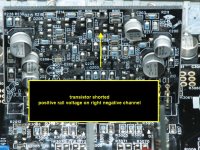
The source of the heat on the driver board is pictured below. (Photo courtesy of Perry Babin)
Is it normally for this card to run this hot?
I have not changed the PS gate resistor value yet, that'll be a job for tomorrow's me with more temperature testing and checking the gate drive.
After idling for just shy of 30 minutes, these are my temps.
PS FETS: 33 C (91.4 F)
Output driver card: 70 C (158 F)
The source of the heat on the driver board is pictured below. (Photo courtesy of Perry Babin)
Is it normally for this card to run this hot?
I have not changed the PS gate resistor value yet, that'll be a job for tomorrow's me with more temperature testing and checking the gate drive.
Attachments
That's extremely hot for the driver board... I think. Maybe someone else will post to say what they've noticed for these driver boards. It figures that you have one of the few Rockford amps that have only one driver board and I never noted the operating temps of these boards.
Are the PS FETs temps with them clamped to the heatsink or not?
Are you saying that the transistor indicated in the photo is the one causing the heating? In the earlier photo, you indicated the FETs lower on the board.
Are the PS FETs temps with them clamped to the heatsink or not?
Are you saying that the transistor indicated in the photo is the one causing the heating? In the earlier photo, you indicated the FETs lower on the board.
I just realized I have a P400-2 stashed away somewhere that likely has the same driver board. I'll pop it on the bench later and check the idle temp. I guess it can pay off to hoard stuff sometimes.
The temperatures I posted are with everything clamped to the heatsink. I'm not quite comfortable enough with this board to power it up out of the heatsink unless specifically instructed to do so.
Yes, the picture I borrowed from you is the component generating the vast majority of the heat at current timee according to my thermocouple.
Prior to adjusting the bias pot, it seemed like it was coming from the lower section as indicated in my first post but that was relying on my fingers and not a proper temperature measuring device. Whether the discrepancy is do to my faulty fingers or turning the pot fully CCW I couldn't say.
To see what's heating the quickest, you can freeze the board with an inverted can of 'canned air'. It will ice up. When you power up, the hot component will immediately be obvious.
Freeze spray and/or canned air is a good idea. I'll have to pick some up the next time I go out. I've seen alcohol used but worry about conductivity and flames, same goes for acetone.
Here's my update
Driver card:
The spare P400-2 has two of the same driver card, each driving one pair of outputs as opposed to one card driving 2 pairs. Max temp on that specific transistor was 40° C (104° F) however the heat the card produced was distributed fairly evenly across the card as opposed to the single hot spot of the card in the P300-1.
I don't understand class AB but I wonder if the heat generation will be more even after setting the bias. (I assume I'll need to contact Rockford to determine where to set it?)
Power supply:
With 47 ohm gate resistance the PS FETs might be heating up slower than before peaking at 31° C. The drive signal looks no different than before to my eye. (The lower temp could be due to lower ambient temperature for this round of tests.)
The P400-2 PS FETs stabilized at 30°C.
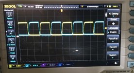
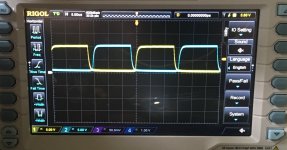
Attached below are the gate drive signals. First picture is with 60.4 ohm (same pic as before,) the second is with 47 ohm and the third is of one bank of the P400-2 in stock form.
(I believe I set the scope as you previously instructed for the two new pictures. If I still have it wrong please let me know.)
Here's my update
Driver card:
The spare P400-2 has two of the same driver card, each driving one pair of outputs as opposed to one card driving 2 pairs. Max temp on that specific transistor was 40° C (104° F) however the heat the card produced was distributed fairly evenly across the card as opposed to the single hot spot of the card in the P300-1.
I don't understand class AB but I wonder if the heat generation will be more even after setting the bias. (I assume I'll need to contact Rockford to determine where to set it?)
Power supply:
With 47 ohm gate resistance the PS FETs might be heating up slower than before peaking at 31° C. The drive signal looks no different than before to my eye. (The lower temp could be due to lower ambient temperature for this round of tests.)
The P400-2 PS FETs stabilized at 30°C.
Attached below are the gate drive signals. First picture is with 60.4 ohm (same pic as before,) the second is with 47 ohm and the third is of one bank of the P400-2 in stock form.
(I believe I set the scope as you previously instructed for the two new pictures. If I still have it wrong please let me know.)
Attachments
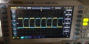
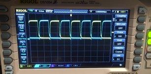

Due to the way that it's covering the markings, it's hard to see but it looks like the overlap is less by at least one minor division with the 47 ohm gate resistors. The 400 is even better with virtually no overlap.
What does the overlap look like (likely none) with only B+ and ground connected?
What does the overlap look like (likely none) with only B+ and ground connected?
Ah, I see what you're seeing at now. Is there a good way to make it easier to read? Perhaps reduce the time scale?
With only B+ and ground there is no drive signal and therefore no overlap. I've seen you suggest in other threads connecting only ground and remote, is that what you meant?
With only B+ and ground there is no drive signal and therefore no overlap. I've seen you suggest in other threads connecting only ground and remote, is that what you meant?
Sorry about that.
The overlap is being caused by the capacitive coupling in the FET.
Are the FETs from a reputable source?
I don't think the slight overlap will cause problems with reliability but it's odd that there is such a difference from the other amp.
The overlap is being caused by the capacitive coupling in the FET.
Are the FETs from a reputable source?
I don't think the slight overlap will cause problems with reliability but it's odd that there is such a difference from the other amp.
No worries, I've read enough in other threads to know what you meant.
All my parts come from Arrow, Digikey or Mouser. These specific parts came from Mouser. I have no interest in creating more problems for myself by using questionable parts.
If you don't think it will cause an issue then I will leave the FETs as-is and add 47 ohm chip resistors to my next parts order.
Is the next step to set the bias and monitor the heat generation of the output driver card?
- Home
- General Interest
- Car Audio
- 2007-ish Rockford P300-1 hot outputs