Hi All
I’m new to the forum, and have absolutely no experience with electronics.
Here’s my project:
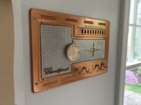
I recently moved into an older house with an intercom system. I repurposed the control panel as a set of hooks for shopping bags etc. and would like to build a guitar amplifier using the guts. The original intercom had a phono in jack, a radio tuner, a speaker, lots of switches, plus the electronics (tubes and other stuff that I can’t yet identify, since I know absolutely nothing about electronics).
Can so help by sharing a source that will teach me the basics (how to identify the parts, and what I need to build a small guitar amplifier)?
Thanks!
I’m new to the forum, and have absolutely no experience with electronics.
Here’s my project:
I recently moved into an older house with an intercom system. I repurposed the control panel as a set of hooks for shopping bags etc. and would like to build a guitar amplifier using the guts. The original intercom had a phono in jack, a radio tuner, a speaker, lots of switches, plus the electronics (tubes and other stuff that I can’t yet identify, since I know absolutely nothing about electronics).
Can so help by sharing a source that will teach me the basics (how to identify the parts, and what I need to build a small guitar amplifier)?
Thanks!
Attachments
I wrote an article almost 30 years ago on the subject. One aspect I pointed out was the initial quality of the piece you'd like to convert to guitar amp use.
The very first gate for your intercom (as source material) would be if it has a power transformer, or is an "AC/DC" design. I recognize the era this intercom was initially built and it could go either way. If it's AC/DC, as a beginner, stay far, far away. Better to get and work with a different hunk of "old iron"!
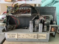
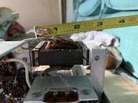
To recognize this, you'll need to know what a transformer is. For an AC/DC set, there'll be only one on the chassis - the audio output transformer. For a set with a transformer based powersupply, there'll be two. Pictures of your chassis would help -
The very first gate for your intercom (as source material) would be if it has a power transformer, or is an "AC/DC" design. I recognize the era this intercom was initially built and it could go either way. If it's AC/DC, as a beginner, stay far, far away. Better to get and work with a different hunk of "old iron"!
To recognize this, you'll need to know what a transformer is. For an AC/DC set, there'll be only one on the chassis - the audio output transformer. For a set with a transformer based powersupply, there'll be two. Pictures of your chassis would help -
Photos here (not sure if attached)
Is it clear?
And is it dangerous to touch anything inside (it is not connected to power)?
Is it clear?
And is it dangerous to touch anything inside (it is not connected to power)?
That seems too small, it may be a filter inductor.
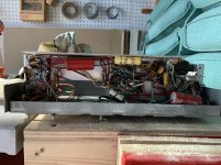
Can you post a photo of the bottom of the chassis?
Can you post a photo of the bottom of the chassis?
Is there any make and model number on it? This is exciting.I'm an idiot, lable on the back, going to look up if there is a schematic.
The tube complement is a 150 mA string adding up to 118V, the left transformer could be power, it is a little big as an output transformer for the size of speaker. The left one could be the output transformer. No luck on a schematic.
The 12AU7 into the 12AV6, or the other way around, then into the 35C5 could make a little Champ. The three tubes add up to 94, could leave the other two in for the ride. Get a box and a 8" speaker, stick the intercom in it, could work.
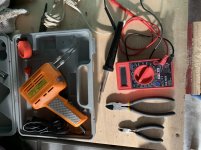
Do you have a multimeter, soldering iron, side cutters, how are you at woodworking?
The 12AU7 into the 12AV6, or the other way around, then into the 35C5 could make a little Champ. The three tubes add up to 94, could leave the other two in for the ride. Get a box and a 8" speaker, stick the intercom in it, could work.
Do you have a multimeter, soldering iron, side cutters, how are you at woodworking?
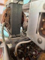
The transformer on the right, toward the outside you have two wires, one enamel coated wire that is wrapped around the hole in the chassis, the other is cloth covered. I can not see where the other wires on the other side of the transformer goes. Could you see and try to describe where they go and if we can see them on the underside picture, what colors they are?
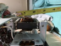
Could you take a closeup picture of the 12AV6 to the transformer area? We are trying to find out where the wires for both the transformers go. also where the line voltage goes. This is to tell us what the transformers do.
There are 2 wires that come from one side of the transformer, a bare one that is soldered to the chassis (circled in gold in the photo) and a green one (circled in white) that connects to a white plastic insulated wire as seen in the second photo. The white wire connects to the “selector switch” (talk, listen, radio mon, radio, phono mon, phono).
Attachments
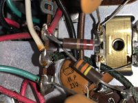
The 2 wires on the other side connect to the 35c5 socket, and to a mini board where the red connects to 2 red Plastic jacketed Wires.
The one wire going to the chassis grounds the output winding, the other side of the winding would go to the speaker or the other area the switch would direct it to. The other side of the transformer, if I am guessing properly is going to pin 7 of the 35C5.
https://frank.pocnet.net/sheets/093/3/35C5.pdf
The other wire will go to the filter capacitor, underneath the chassis, the red paper cylinder, I am guessing it should have at least three wires out of it, two red and a black by the looks of it.
What would be good to know is what the other transformer is doing. I am guessing it is going to the switches and the other winding to the 12AU7.
Here is a theory on a guitar amp
How Amps Work
YouTube
https://ax84.com/archive/ax84.com/static/p1/P1_Theory_Document.zip
http://www.guitarstudio.tv/documents/Designing-V-T-Amplifiers.pdf
http://www.tubebooks.org/Books/crowhurst_basic_1.pdf
http://www.tubebooks.org/Books/crowhurst_basic_2.pdf
http://www.tubebooks.org/Books/crowhurst_basic_3.pdf
http://tubes.nekhbet.com/pdf/ga699ac.pdf
http://ken-gilbert.com/images/pdf/ga100ac.pdf
https://www.tiffe.de/roehren/ga200ac.pdf
http://ken-gilbert.com/images/pdf/ga300ac.pdf
http://ken-gilbert.com/images/pdf/ga400ac.pdf
This is clearly a HOT CHASSIS amplifier. The OT is a little large but an intercom is larger and priced higher than a $9.98 radio. The little transformer steps-up "microphone (speaker) signal to grid.
This is clearly a HOT CHASSIS amplifier. The OT is a little large but an intercom is larger and priced higher than a $9.98 radio. The little transformer steps-up "microphone (speaker) signal to grid.
Thought that was the little guy, and why it was by the 12AU7. Going to have to get an isolation transformer for the power.
The large transformer is the audio output transformer.
The small transformer is the audio input transformer.
The speaker is also used as the microphone.
The remote stations have similar speakers.
The speaker impedance may be 32 or 45 Ohms rather than 4, 8, or 16.
The reason for high impedance is because of the very long run of wire.
Probably, a three wire flat 'zip' cord goes to each station. It has the input, ground (common) and output signals.
The switching is clever but simple so that any station can be surreptitiously listened in on (like a baby moniotor), or can be included or removed from a call originating from the master station. Each station should have a push-to-speak switch and a volume knob.
The manual for a similar unit, the Nutone 2055 and 2056 is attached and may be helpful. There are many videos on youtube for nutone intercoms. That was the biggest brand, and still is, withthe modern units having bluetooth and other diddlybobs included in them.
Since you have a nice row of switches, you have an opportunity to use them as "voicing" switches, just like the stops on an electronic organ simulated many different instrument sounds. This was done on some early instrument amps.
You have room to add an isolation transformer inside a guitar amp case. You can also use this to power other circuits for effects and other stuff.
You may find that the input gain is low for guitar. that is, the small input transformer feeds a tube, but it is a step up transformer, so an extra stage may be needed. Thus the suggestion for an isolation transformer large enough to power the chassis, plus another small power supply for add-ons.
The unit is old. these ran 24x7, so check the tubes.
Lastly, the thing is made for whatever AC Volts the filaments and any series resistor add up to. It may prefer 115V or 117V rather than 125V, so consider tailoring your isolation transformer secondary for that, or changing/adding your series resistor in the filament circuit, or whatever means required to properly run the filaments for best tube life.
Attachments
- Status
- Not open for further replies.
- Home
- Live Sound
- Instruments and Amps
- Beginner help requested