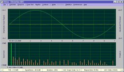
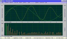
Using the DAC outputs of a L22 in single ended (SE) mode* means trouble. Although it performs reasonably well above 1kHz, below say 100Hz, the distortion increases drastically. At 16.35Hz THD rises from -117.6dB (balanced mode) to -75.9dB (SE mode). That's 100 times more! See fig1. vs fig.2 (Another measurement reveals an increase of 'only' 30 times).
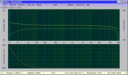
Also the frequency response is affected in SE mode. At 10Hz it drops to about -3dB, while in balanced mode only -0.2dB. See fig. 3 (balanced) vs fig.4 (SE).
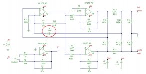
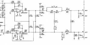
The reason for this flaw appears to be a X5R ceramic capacitor in the signal path. See fig. 5, C5. The distortion is not only a result of a wrong type of dielectric but also the value of only 100nF is way too low. As a result, the output current of op-amp X3 rises far beyond its limit at low frequencies, over 25mA. This also introduces more distortion, probably the main cause.
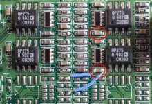
And the remedy? Simply short this evil capacitor, in both channels of course, see fig. 6 where to find them**. Initially I was afraid of a larger off-set voltage at the outputs. But that wasn't the case. It was even lower after shortening these caps.
BTW, I also experimented with other op-amps: A LM4562 instead of the original OP275's, but THD figures were about the same. Maybe OPA1656 will do better.
Cheers,
E.
*XLR pin3 shorted to ground (pin1)
** The two blue wires were just for experimenting with larger caps connected via the 25 pins delta connector from the outside world.
Comment from Bob Bauman at Lynx Studio:
"I will not confirm that your schematic of the line driver is correct because that is proprietary information. However I will say that there was one 100nF cap that was replaced with a zero ohm resistor in later renditions of the line driver."
Also the frequency response is affected in SE mode. At 10Hz it drops to about -3dB, while in balanced mode only -0.2dB. See fig. 3 (balanced) vs fig.4 (SE).
The reason for this flaw appears to be a X5R ceramic capacitor in the signal path. See fig. 5, C5. The distortion is not only a result of a wrong type of dielectric but also the value of only 100nF is way too low. As a result, the output current of op-amp X3 rises far beyond its limit at low frequencies, over 25mA. This also introduces more distortion, probably the main cause.
And the remedy? Simply short this evil capacitor, in both channels of course, see fig. 6 where to find them**. Initially I was afraid of a larger off-set voltage at the outputs. But that wasn't the case. It was even lower after shortening these caps.
BTW, I also experimented with other op-amps: A LM4562 instead of the original OP275's, but THD figures were about the same. Maybe OPA1656 will do better.
Cheers,
E.
*XLR pin3 shorted to ground (pin1)
** The two blue wires were just for experimenting with larger caps connected via the 25 pins delta connector from the outside world.
Comment from Bob Bauman at Lynx Studio:
"I will not confirm that your schematic of the line driver is correct because that is proprietary information. However I will say that there was one 100nF cap that was replaced with a zero ohm resistor in later renditions of the line driver."
Attachments

Could you explain more explicitly why you think it is not good? Just because of that evil C5 or did you discover more flaws?
Last edited:
That is an active balanced circuit that will have a constant output even if one side is grounded. The cap is a problem in that application. Also when I played with it in sim trying to get 50 Ohms to work I never could. All the resistors need to scale for that to work properly (i.e. 1V into a 600 Ohm load is 1V even if one side is shorted). The plus is that its good at dealing with significant common mode which is why I pursued it. Attached is a simulation that I started from. The Lynx looks simpler and maybe i should try it. I don't think Mike Lynch added complexity without good reason.
Attachments
Squinting at my board it looks to have caps. Jumpering is not too hard. The weakness in the opamps would be driving a lowZ load. The new ones from TI for headphones would be a good option but those are duals and the board is setup for singles.
This core of this is an interesting circuit that looks to have its genesis in the HP8903 circa 1980. The engineer (George Pontis) walks through the operation starting on page 10 of the PDF linked below. With the input shorted, a voltage can be applied to both the outputs and you can observe zero current flowing suggesting isolation (as long as you are withing the supply rails give or take). Pontis indicates the output stage on the 8903 had to be ground referenced given the number (roughly 30!) of digital control signals they had. So, rather than the obvious approach of an isolated supply and digital isolators, Pontis came up with this circuit and kept the output ground referenced but allowed it to float.
Starting around 2015, a range of very cheap and simple push-pull ICs emerged to generate isolated supplies. Power was limited to a watt or three, but they run open loop and rely on a very tightly spec'd transformer with a clearly spec'd lower bound on volt*time product. Around that same time, some very economical digital isolators also appeared. Taken together, it became very easy to move a lot of digital signals across an iso barrier and generate a true 2-3W isolated supply with several kv of isolation.
Given the launch date on the L22 (2002?), there probably wasn't an economical way to generate a true isolated output, and so falling back to this approach made sense. But no idea why they added all the other stuff around Pontis' original core. What usually happens is a first product uses the circuit, and then that engineer leaves, and the new engineer doesn't quite understand the circuit and encounters a problem, and they starting adding caps to try and make the circuit behave. And later that person leaves, and the next person is even more confused at what they are looking at in the product evolution. But they don't dare touch it without understanding it, and so they replicate it with some tweaks and hope it works. Maybe that happened here and that's how it morphed from the original.
https://www.keysight.com/upload/cmc_upload/All/EPSG085898.pdf
Regarding that evil capacitor (C5) maybe they were afraid of latch-up during start-up or overdrive conditions and inserted a capacitor in the positive feedback path to avoid it.
Shows the dangers of only running THD tests at 1kHz I suspect - this mistake should have been caught, so I suspect a late change with minimal testing.
The pad size looks too small for a 100nF filmcap, so its unlikely to be a manufacturing substitution.
The pad size looks too small for a 100nF filmcap, so its unlikely to be a manufacturing substitution.
- Home
- Design & Build
- Equipment & Tools
- Design flaw Lynx L22 sound card