Rookie question from a non-audio technician-
A 36pF mica capacitor on one channel has ~1 Vdc with DMM leads across the capacitor leads. The other channel, same component shows zero Vdc.
The capacitor that measures 1 Vdc is bad?
I ordered new mica caps, (expensive compared to other components), but won't be here for a few days and I'm trying to learn.
Most likely both capacitors are just fine, but if one of them is damaged, it is more likely to be the one with 0 V across it.
Unless its the very old type and not a silver mica type I would be dubious that there is leakage in the capacitor.
I have a large collection of quality silver mica capacitors bought decades ago when they were cheap not one has leakage.
As a trial replace it with a quality polystyrene type and check if the same voltage occurs .
Those low values are usually used for stability purposes in high frequency/liability to HF oscillation situations but you haven't provided much information, what is the voltage it is connected across / is it an inter-stage capacitor ?
I bet some external source is placing 1V DC across it.
Wouldn´t fault the capacitor per se, which by definition is an open circuit to DC.
Please show the schematic to go beyond the adivination stage.
Wouldn´t fault the capacitor per se, which by definition is an open circuit to DC.
Please show the schematic to go beyond the adivination stage.
It is a Marantz 1200 power amp board.
The capacitor in question is C501. The amp is oscillating and the service manual recommends to check C505, C506, C509 and C516. I replaced C516 since I had one here at home. (C516 = 0.1 uF) I decided to check all the mica caps, but my DMM won't go any lower than the nF range.
I checked voltage on C501 because my DMM doesn't go low enough and it is located towards the edge of the board. It has been squashed down on the board.
The new mica caps should be here tomorrow.
Thanks for your replies.
Attachments
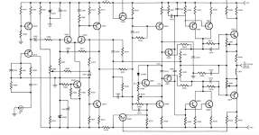
If you could provide the values of CR501, R548, R547, R549 and R551 and the type number of Q519, we could calculate what the expected DC voltage across C501 would be.
C501 seems to be part of the input slew rate limiting components which normally (in itself ) would not induce HF oscillations but affect distortion factors , it would need to be inputting HF from another part of the circuit to cause a fault condition.
C516 is part of the Zobal circuit to take care of re-entry by loudspeaker voice coils although it does help with some HF oscillations .
I would check out the compensation capacitor which provides feedback to keep the amplifier from oscillating , it should be a low value but varies from circuit to circuit -5pf up to 100pf.
As MarcelvdG says (above ) we need to know the values of all the components you mention.
Capacitance values are as follows:
C501 - 150pf +/- 10%, 100V
C505 - 47pf, +/-5%, 100V
C506 - 680pf, +/-5%, 100V
C509 - 36pf, +/-5%, 300V
C516 - 0.1uf, +/-10%, 250V (this cap has been replaced, it was reading over 0.22uf)
I'm not able to test any caps >1000pf with my DMM.
Which is the compensation capacitor?
Thank you for your replies!
Duke
If you could provide the values of CR501, R548, R547, R549 and R551 and the type number of Q519, we could calculate what the expected DC voltage across C501 would be.
MarcelvdG,
CR501 - 1N9678 diode, all measure ~+/-17.8Vdc, except for one on the same channel that has the C501 with the 1Vdc measurement. This diode measures +18.7Vdc.
R548 - 2.7K Ohm
R547 - 2.2K Ohm
R549 - 10K Ohm
R551 - 270K Ohm
Q519 is 2N4250
Just went and measured the Q519 on both channels.
Right channel
Emitter -15.43
Base -14.34
Collector -1.098
Left channel
Emitter -15.43
Base -14.81
Collector 0.96
What the? I removed all transistors and tested with the transistor tester from China. This was about a month ago.
But, would voltage between the emitter and base indicate a bad transistor or that it is passing current from another component?
I will remove one leg of each resistor and check for shorts or open...
It looks like you have a distributed compensation layout IE- there is not one single feedback capacitor but several in various positions .
Q519 at the input is a low noise silicon transistor used for audio purposes (now obsolete ) ,as such there should be no leakage , I have just tested a BC560C audio pnp transistor for leakage at 2.50ma as well as others --zero leakage .
Old germanium transistors do have leakage but are not generally used in modern audio design as they introduce problems in most designs.
If you figures are right you have a high input impedance which would keep the base at a higher level ,
A very simple way to test a BJT is to use an analog test meter with ,in your case for a pnp transistor test - take it out and connect the positive lead probe to the base and tap the collector and emitter with the negative probe you should get the same low resistance on either leg , on the BC560 using an old AVO8 I get approx -25/28 ohms.
I have a feeling your problems are not directly at the input but in other parts of the circuit , do you have a ,scope ?
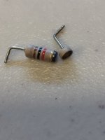
Hello duncan2-- This morning I spent a few hours unsoldering one leg of every resistor on each channel and measuring with the DMM. Of course, the last one was broken. That's R545 on the right channel. I'm going to check all the resistors on the other channel. And, I'm scrounging around for a 1K resistor. Another audio nut has one, lives nearby, but I'll have to wait until tomorrow.
Also, I've learned that one channel oscillating can cause the other channel to oscillate/have other problems. Or, that's how it seems. I haven't finished checking the other channel...
Also, I've learned that one channel oscillating can cause the other channel to oscillate/have other problems. Or, that's how it seems. I haven't finished checking the other channel...
Attachments
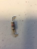
Found another bad resistor on the other power amp board- R505, 470k Ohm resistor.
I'm done for today.
Thanks for your replies, Duncan2!
I'm done for today.
Thanks for your replies, Duncan2!
I bet those resistors were fine, and broke only because you messed with them.
Removing *all* parts for static measurement is a sure way to damage the unit and a very iffy way to find faults.
Removing *all* parts for static measurement is a sure way to damage the unit and a very iffy way to find faults.
MarcelvdG,
CR501 - 1N9678 diode, all measure ~+/-17.8Vdc, except for one on the same channel that has the C501 with the 1Vdc measurement. This diode measures +18.7Vdc.
R548 - 2.7K Ohm
R547 - 2.2K Ohm
R549 - 10K Ohm
R551 - 270K Ohm
Q519 is 2N4250
The DC voltage across C501 should be somewhere in between 0.357 V and 1 V. If it isn't, that can still be due to just about anything.
How did you determine that the amplifier is oscillating? Does it stop when you disconnect the positive side of C502 on the oscillating channel and connect it to ground?
The measurements on Q519:
Emitter 1V
Base 0.5V
Collector 14.5V
Just went and measured the Q519 on both channels.
Right channel
Emitter -15.43
Base -14.34
Collector -1.098
Left channel
Emitter -15.43
Base -14.81
Collector 0.96
Does this mean that the values are not reproducible?
For what it's worth, if everything worked well, you should get something like this:
Base: in between 0.357 V and 1 V
Emitter: in between 0.857 V and 1.8 V
Collector: around -18 V
Then again, when an amplifier is oscillating, that usually results in weird DC readings that can even change depending on how close you are to the oscillating circuitry.
I bet those resistors were fine, and broke only because you messed with them.
Removing *all* parts for static measurement is a sure way to damage the unit and a very iffy way to find faults.
All parts were not removed. I was attempting to determine what caused the voltage I measured. I'm not a technician or EE, but I do know that shorted or open resistors would cause the oddball voltage. The broken resistor fell apart when I touched it, literally. It's location in the circuit tells me that it most likely was the cause of the measurement I was seeing, since it's located in the over current protection area of the board.
This amp has given me a chance to learn something about audio electronics during the stay at home time. All helpful advice is appreciated.
On other internet forums, the advice is to send the amp across the country for repair, these amps are known to have problems, blah, blah, blah. Worst case scenario is I'll build Leach Amp boards and convert it into a Leach Amp internally. And, I might learn a few things.
- Home
- Amplifiers
- Solid State
- Testing capacitor in circuit