I've built this headphone amp as detailed here and I'm not getting any sound out from it. I can feel (through my cheapo headphones used for testing) that the driver gets warm.
The power supply is OK, feeding +/-12
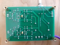
I've done some basic checking - so as far as I can see all polarities are observed and the correct parts installed according to the BOM (the empty holes are for optional diodes according to the BOM).
I've cleaned the boards again and checked for obvious shorts.
I've swapped out the BUF634s and LM4562s
What should I look for now?
The power supply is OK, feeding +/-12
I've done some basic checking - so as far as I can see all polarities are observed and the correct parts installed according to the BOM (the empty holes are for optional diodes according to the BOM).
I've cleaned the boards again and checked for obvious shorts.
I've swapped out the BUF634s and LM4562s
What should I look for now?
Attachments

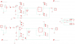
D1A and A1B are not placed, both anodes to the gain-amp outputs, cathodes to the minus rail. Odd that is.
Remove the opamps & buffers and check for wrong dc voltages.
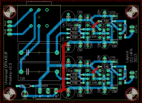
Verify all solderings on the (upper) ground plane and make sure they're connected to the 0V from the power supply (I had once a serious time lost finding this stupid mistake of myself...); you cannot see if the soldering under the power connector is ok - the power connector sits on top of it. Same applies to the attanuator, but if the ground is missing there you have no attanuation at all, only maximum volume.
Remove the opamps & buffers and check for wrong dc voltages.
Verify all solderings on the (upper) ground plane and make sure they're connected to the 0V from the power supply (I had once a serious time lost finding this stupid mistake of myself...); you cannot see if the soldering under the power connector is ok - the power connector sits on top of it. Same applies to the attanuator, but if the ground is missing there you have no attanuation at all, only maximum volume.
Thanks for the hint MarsBravo.
I removed the opamps and buffers and checked for DC. On the LM4562 I discovered the + wasn't going where I thought it did! Upshot, the LM4562 has the +V on pin 8 whereas the board is configured for +V on pin 7.
My own stupid fault for not checking the datasheet. The original article called for a LME49710 which I couldn't get and I had it in my head that the 4562 was the same chip, but it is the same as the 49720. Live and learn.
Thanks again for taking the trouble to look.
Yes, this is a trap for the unwary, single and dual opamps in 8-pin packages have different V+ pin. Many single opamps have different compensation and offset schemes anyway so as always remember to check the datasheet for every part. (Having said that dual opamps in 8-pin packages seem always to be pinned-out identically).
Another trap that can get you is quad opamps v. quad comparators like the LM339 - totally different pinout.
Another trap that can get you is quad opamps v. quad comparators like the LM339 - totally different pinout.
Oh yes, that other blunder of mine: put in a 339 where a 324 was noted on the top silk...Another trap that can get you is quad opamps v. quad comparators like the LM339 - totally different pinout.
Sounds like you've found the problem Neal - you need single OPAs for this 🙂
@MarsBravo: The "diodes" are CRDs (= constant current sources) for experimenting with optional class A biasing of the opamps as explained here: Biasing Op-Amps into Class A
@MarsBravo: The "diodes" are CRDs (= constant current sources) for experimenting with optional class A biasing of the opamps as explained here: Biasing Op-Amps into Class A
Yes, this is a trap for the unwary, single and dual opamps in 8-pin packages have different V+ pin. Many single opamps have different compensation and offset schemes anyway so as always remember to check the datasheet for every part. (Having said that dual opamps in 8-pin packages seem always to be pinned-out identically).
Lesson learned!
In some ways it's good to have things go wrong, it (hopefully) makes you more diligent next time and you always learn something, which is always good.
Sounds like you've found the problem Neal - you need single OPAs for this 🙂
I think I'd got complacent, I've got so used to using dual opamps, which, as Mark says, usually have the same pinout.
Yet another of your projects, I've done a few of them now, so thanks for making them available, it's much appreciated.
Hi Tachyon, there's a BOM on Nisbeth's site.Hi NealJ
What component values did you use? I see they're not listed on the schematic.
Well, I ordered some single opamps and still got sent some dualsSounds like you've found the problem Neal - you need single OPAs for this 🙂
 . Some force doesn't want this finished.
I've finally had time to get back to this. I have OPA134 in now but one of the BUF634s gets hot and distorts the sound (oscillation?).
Any ideas please?
Any ideas please?
- Home
- Amplifiers
- Headphone Systems
- Problem with buffered opamp HPA