The Thorens TD125 used a Wein bridge oscillator to drive the motor, firstly using discrete components and then in the Mk2 709/714 op amps.
With the top-end TD320 they used an RC oscillator (schematic attached). However I am puzzled by this circuit. It seems to most closely resemble a quadrature oscillator using the two top left op amps. However a quadrature oscillator requires 3 RC segments whereas this only appears to have 2 ( consisting of the 1% toleranced caps and resistors, I assume).
Can anyone explain how this works please?
Attachments
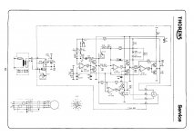
It is a state variable filter arrangement set up to be an oscillator and a dual BTL amp to drive the motor. The first 2 opamps (sections A & B of the quad) are integrators and each one creates a 90° shift; this provides the sine and cosine outputs to the motor via the xstr amps. Section D of the quad opamp inverts the sine phase to complete one of the BTL amp sections. The final C section of the opamp inverts the cosine signal to complete the second BTL amp and also provides the final 180° phase shift for the oscillator (the output is feed back in phase (90°+90°+180°) to the input of the first integrator). Amplitude control is done by the 2 back to back zeners to prevent the level from increasing indefinitely so the integrators produce sinewaves.
Many thanks Pyramid for your speedy reply. That's made it pretty clear even for me!
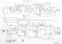
You may be interested in the attached schematic for another Thorens turntable, the TD520. This was a kind of hi-end version of the 300 series and could take 12 inch tonearms. I have one running my own design linear-tracking air-bearing arm.
The design appears to be pretty much the same except there are a couple of extra op amps for the speed adjusters (as buffers I believe).
All the stuff at the top appears to be for the synthesised strobe light (wall wart connection so no mains I guess).
I can't find any source on the web that has a shot of the schematic that is actually legible, unfortunately!
Once again, many thanks for your explanation. Much appreciated!
Attachments
quadrature uses either 2 90 degree shifts and an inverter, or 4 90 degree shifts. Integrator gives a solid 90 degree shift, but only if each is an active stage (gets the pole right close to origin)
Some oscillators use 3 60 degree RC passive shifts plus inverter when only a single output is needed, I think that's what you were confusing with quadrature. Such circuits have poles not at the origin so each RC stage cannot shift a whole 90 degrees, hence the need for three stages, but only the inverter needs to be active.
Some oscillators use 3 60 degree RC passive shifts plus inverter when only a single output is needed, I think that's what you were confusing with quadrature. Such circuits have poles not at the origin so each RC stage cannot shift a whole 90 degrees, hence the need for three stages, but only the inverter needs to be active.