Hi All,
Hoping to get some feedback on the crossover for a project of mine. I am crossing over a SEAS 27TDFC H1189 to a TB W5-1685. I have developed a 2nd order high-pass/low-pass crossover (as I feel the drivers lend themselves well to 2nd order networks) with the high-pass at 2080Hz and the low-pass to the TB at 3360Hz.
I initially started with both being at 2300Hz but landed on these values after some tweaking on VituixCAD (I also added a 4ohm resistor to the SEAS and wired it in reversed phase to avoid a large trough in the frequency response).
Just hoping to have some feedback as this is a first for me. I also question my calculations for the low pass filter as the 3360Hz doesn't seem to correlate on the graph with the blue line for the TB W5-1685. Using equation 1/(2pi√(L*C)).
Graphs, circuit, and datasheets attached.
Thanks!
Attachments
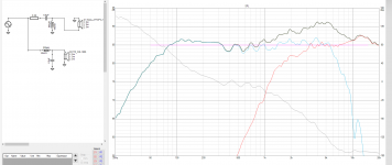
That woofer series inductor and parallel capacitor values are too small, the woofer response is total flat up to 5 kHz hence the large and wide peak around that region. This peaky on-axis response is your target?
Tweeter response looks fine, I would adjust the woofer to cross over at 2-3 Khz
if your calculations were based on resistive values, not actual values resistance values at the chosen crossover frequency leads to errors, which is why you are surprised by differences from calculated values.
Take YDSR's advice and change values in Xsim by a few more clicks to flatten the response and get a more balanced result.
You will still have to listen to the design and probably tweak component values to taste.
Thanks both. You're right it wasn't looking good with the peak at 5K, I think I was just shying away from an overly large capacitor value from a cost perspective. The attached image seems to be about as flat as I can get it there, a slight peak after 7K still though.
Any other thoughts?
Any other thoughts?
Attachments

Off axis you should find that the peak above 7 Khz becomes less pronounced and may give a balanced result.
Speaker firing straight down the room and you sitting in between for less HF. Listening in your own room will tell you if it needs a tweak.
Speaker firing straight down the room and you sitting in between for less HF. Listening in your own room will tell you if it needs a tweak.
As an exercise in xo sims try these:
- reduce the woofer shunt cap and increase the series inductor
- if you still can't get rid of that broad mid peaking, add a small value resistor in series with the cap and adjust to see if that will help
- if the peaking is still there you may need to use a shallow but wide notch filter
- on the tweeter, move the resistor from before the xo filter to after it. The way the tweeter FR is attenuated varies with where you place it in the circuit. You may need to adjust the xo values afterward. You can also split the resistors to both before and after the xo components to try and get the FR you are looking for.
However, it isn't much more than a learning exercise right now because you haven't included baffle diffraction effects yet. I'm going to also bet that drivers' acoustic center info may be missing too. Possibly minimum phase hasn't been extracted from your files as well. Could be wrong there though. Also besides working to get a flat FR, you should be working to align each driver's phase in the overlapping region of the xo. Can't tell where that is at because in VCAD, that's on another graph not attached.
Try this thread - So you want to design your own speaker from scratch! - to give more info on the above.
If by this you mean that the response trace didn't initially include phase information, then ok, calculate it. Otherwise this is an involved topic.Possibly minimum phase hasn't been extracted from your files as well.
I've attached the latest crossover with all graphs shown. I haven't interpreted a phase graph before so will have a read through wintermute's thread tonight to see if it gives me a better understanding. What is your interpretation of the phase graph?
Thanks for all the info from everyone.
Thanks for all the info from everyone.
Attachments
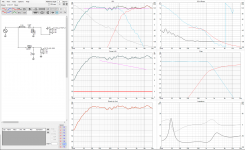
Your xo is at about 1700Hz. A good rule of thumb is to try to get good phase alignment 1 octave above and 1 octave below it. So that's between 850Hz and 3400Hz. In other words, in the region where both drivers are contributing equally to the summed output.
Looking at your phase graph, the phase is fairly well aligned between about 300Hz and 1000Hz. Not so much between 1000Hz and above.
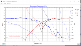
A little test to see how well phase is lined up in the xo region is to reverse the polarity of 1 of the drivers. That will change the phase relationship considerably and the result will be a deep drop in the summed FR in the xo region, referred to as the reverse null.
Attached are examples from another speaker. Pic 1 shows very good phase alignment between about 700Hz and 2500Hz. A little better alignment higher up in frequency would be ideal but this is more than acceptable. Pic 2 shows the same speaker with the polarity on the tweeter reversed - a deep and wide reverse null.
Looking at your phase graph, the phase is fairly well aligned between about 300Hz and 1000Hz. Not so much between 1000Hz and above.
A little test to see how well phase is lined up in the xo region is to reverse the polarity of 1 of the drivers. That will change the phase relationship considerably and the result will be a deep drop in the summed FR in the xo region, referred to as the reverse null.
Attached are examples from another speaker. Pic 1 shows very good phase alignment between about 700Hz and 2500Hz. A little better alignment higher up in frequency would be ideal but this is more than acceptable. Pic 2 shows the same speaker with the polarity on the tweeter reversed - a deep and wide reverse null.
Attachments
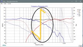
Okay thanks for the example. Lets say in this setup I've attached here where it's consistently out of phase by about 40 degrees. Would it be possible to baffle step the tweeter from the woofer to try and counteract the phase difference in that region?
I imagine I could average the wave lengths in that frequency region (the two octaves) and then multiply by the phase difference to calculate the best distance to step it back by?
I imagine I could average the wave lengths in that frequency region (the two octaves) and then multiply by the phase difference to calculate the best distance to step it back by?
Yes you can alter the phase relationship by changing the physical alignment of the drivers in the vertical plane - either by moving the tweeter back in a stepped baffle type of configuration or by tilting the baffle backwards.
But - this is totally premature. You don't have the correct info in your files loaded into the program yet, baffle diffraction, acoustic centers and minimum phase as I mentioned in my 1st post. Do all of that first before considering changing the physical alignment because I suspect that there is no real need for it. In other words, what you are seeing right now is not correct.
If you need some help getting that done, myself and I would think others here are perfectly willing to help.
Thanks for the offer to help out. I imagine my front baffle is not going to be ideal by any means as it has a CNC'd polygon design and the whole thing is recessed into the enclosure by about 8mm.
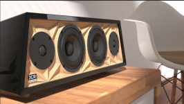
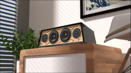
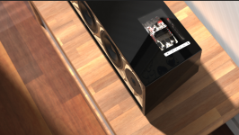
To give you some background this is a project I have been developing for several months (the majority of time so far has been invested in developing a PCB). Now this is complete I have completed the CAD for the speaker having calculated and 3D printed the BRP (but can't get to the workshop for obvious reasons). I realise I have compromised on a few audio aspects for the design (such as the drivers being paired horizontally and overall size) but the idea is this a HiFi speaker for living rooms, student accommodation, parties, etc. which remains semi-portable with a large lithium-ion battery.
Some renders attached. It would be good to discuss some of these concepts I'm unfamiliar with as I'm coming from a design engineering background but this is also my first speaker project where I've delved deeper into the science and simulated aspects.
Attachments
Quite gorgeous. But function is definitely the slave to form on this one.
Definitely have a solid read through the designing thread I linked to before. Also wondering what f3 you are shooting for? Is the speaker meant to be paired with a sub or to stand on its own?
Definitely have a solid read through the designing thread I linked to before. Also wondering what f3 you are shooting for? Is the speaker meant to be paired with a sub or to stand on its own?
Thanks 🙂 I've had a read through the document, lots of useful stuff!
This is a standalone speaker. The internal volume is 14000cm^3 (accounting for drivers, etc.) with a tuning frequency of 35Hz. F3 of 68Hz. Wasn't expecting anything amazing in something so small. My original intention was to have a sealed enclosure with a powered sub underneath but the electronics got out of scope with active crossovers, twin amps, etc. Would also be difficult to have it battery powered as efficiency would be way down on the floor. Could potentially be a version 2.
This is a standalone speaker. The internal volume is 14000cm^3 (accounting for drivers, etc.) with a tuning frequency of 35Hz. F3 of 68Hz. Wasn't expecting anything amazing in something so small. My original intention was to have a sealed enclosure with a powered sub underneath but the electronics got out of scope with active crossovers, twin amps, etc. Would also be difficult to have it battery powered as efficiency would be way down on the floor. Could potentially be a version 2.
Attachments

- Home
- Loudspeakers
- Multi-Way
- 2-Way Crossover Design