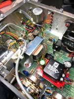
I recently made several modifications to a Urei LA-4 leveler/compressor to improve noise and dynamic response performance. The LA-4 seen in the attached photos was initially upgraded by a previous owner who used one of the well-known vintage audio upgrade services. That service upgraded both RC4136 op-amps with premium types which is curious since one of the RC4136 devices is used strictly for gain control; audio does not pass through the device. As such, I decided to change the gain control IC back to a 4136. However,I did conduct a systematic upgrade of the LA-4’s audio path and that’s the subject of this post.
The stock Urei LA-4 (early version) audio path is as follows:
4136 è4136 èLDR è4136 èLM301A èPP AB driver èUrei Output Transformer.
And after the mods:
Jensen JT-11P line input transformer è AD797 è LDR è AD797 è 990C+ Discrete Op-amp è Jensen JT-11 DMCF high-nickeloutput transformer.
Nichicon Muse UES bipolar electrolytic caps with paralleled film caps are used for inter-stage audio coupling and replace the back-to-back tantalum caps which were used by Urei to create a quasi-non-polarized capacitor.
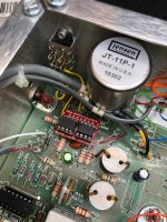
Noteworthy here is that the 4136 differential input stage was changed to a line input transformer, just like the Urei LA-3A. Although the stock 4136 differential input topology has a CMRR adjustment, it’s vastly inferior to a 3-stage instrumentation op-amp circuit. The stock configuration cannot maintain high CMRR across a broad range of spectrum, especially at RF frequencies where high CMRR is required (e.g., in a co-locate broadcast facility with a nearby AM or FM transmitter).
Although there are some good 3-stage input designs, some of which are on monolithic chips, I elected to utilize the Jensen JT-11P for its exceptional wideband CMRR characteristics. Careful attention was paid to the secondary load impedance and R/C overshoot compensation network. The transformer's load impedance remains constant regardless of the LA-4’s High/Low switch setting. That was accomplished by reversing the inverting and non-inverting inputs at IC-1C such that the transformer terminates into the non-inverting input and the switchable gain leg is now shunted with resistors to signal ground.
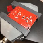
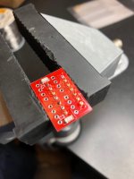
After the input transformer, two sections of the 4136 were replaced with AD797 op-amps. I designed my own PC boards to convert two sections of a 4136 to an AD797 pair and includes SMD pads for additional distortion cancellation caps. Analog Devices specs the use of the added cap when the voltage gain factor A > 10 (i.e., > 20 dB).
Next, the LM301A and PP AB sections were gutted and replaced with a John Hardy 990C+ discrete op amp module. The 990 includes a complimentary-symmetry pair of MJE-171/181 high-current driver transistors biased class AB. The990C+ is installed on a custom PC board with ground plane that I recently designed. The board includes power supply bypass and decoupling. The +/-18V power entry bus is further filtered with two 100 uF “reservoir” caps in parallel with 0.1 uF NP0 MLCCs.
Finally, the Urei output transformer was replaced with a high nickel core composition Jensen JT-11 DMCF. This transformer exhibits low distortion even at very low frequencies when operating at a high output level.
At a later time, I will add a pair of 990C+ modules to create an active output transformer as a rear panel connection option. The PC board design for that option is now complete.
The changes I’ve described are primarily intended to lower system noise, increase input CMRR and improve slew rate over the stock design. The replacement components also exhibit very low THD, TIM, and IMD characteristics. However, the reality is that any improvement in THD is mostly masked by the non-linear cadmium sulfide LDR cell. The LDR gain control mechanism is the equivalent of a potentiometer with the upper voltage divider composed of carbon, while the lower shunt divider section is composed of cadmium sulfide.
Paul
The stock Urei LA-4 (early version) audio path is as follows:
4136 è4136 èLDR è4136 èLM301A èPP AB driver èUrei Output Transformer.
And after the mods:
Jensen JT-11P line input transformer è AD797 è LDR è AD797 è 990C+ Discrete Op-amp è Jensen JT-11 DMCF high-nickeloutput transformer.
Nichicon Muse UES bipolar electrolytic caps with paralleled film caps are used for inter-stage audio coupling and replace the back-to-back tantalum caps which were used by Urei to create a quasi-non-polarized capacitor.
Noteworthy here is that the 4136 differential input stage was changed to a line input transformer, just like the Urei LA-3A. Although the stock 4136 differential input topology has a CMRR adjustment, it’s vastly inferior to a 3-stage instrumentation op-amp circuit. The stock configuration cannot maintain high CMRR across a broad range of spectrum, especially at RF frequencies where high CMRR is required (e.g., in a co-locate broadcast facility with a nearby AM or FM transmitter).
Although there are some good 3-stage input designs, some of which are on monolithic chips, I elected to utilize the Jensen JT-11P for its exceptional wideband CMRR characteristics. Careful attention was paid to the secondary load impedance and R/C overshoot compensation network. The transformer's load impedance remains constant regardless of the LA-4’s High/Low switch setting. That was accomplished by reversing the inverting and non-inverting inputs at IC-1C such that the transformer terminates into the non-inverting input and the switchable gain leg is now shunted with resistors to signal ground.
After the input transformer, two sections of the 4136 were replaced with AD797 op-amps. I designed my own PC boards to convert two sections of a 4136 to an AD797 pair and includes SMD pads for additional distortion cancellation caps. Analog Devices specs the use of the added cap when the voltage gain factor A > 10 (i.e., > 20 dB).
Next, the LM301A and PP AB sections were gutted and replaced with a John Hardy 990C+ discrete op amp module. The 990 includes a complimentary-symmetry pair of MJE-171/181 high-current driver transistors biased class AB. The990C+ is installed on a custom PC board with ground plane that I recently designed. The board includes power supply bypass and decoupling. The +/-18V power entry bus is further filtered with two 100 uF “reservoir” caps in parallel with 0.1 uF NP0 MLCCs.
Finally, the Urei output transformer was replaced with a high nickel core composition Jensen JT-11 DMCF. This transformer exhibits low distortion even at very low frequencies when operating at a high output level.
At a later time, I will add a pair of 990C+ modules to create an active output transformer as a rear panel connection option. The PC board design for that option is now complete.
The changes I’ve described are primarily intended to lower system noise, increase input CMRR and improve slew rate over the stock design. The replacement components also exhibit very low THD, TIM, and IMD characteristics. However, the reality is that any improvement in THD is mostly masked by the non-linear cadmium sulfide LDR cell. The LDR gain control mechanism is the equivalent of a potentiometer with the upper voltage divider composed of carbon, while the lower shunt divider section is composed of cadmium sulfide.
Paul
Attachments
Last edited:
> intended to lower system noise, increase input CMRR and improve slew rate
Does it? Tests?
> any improvement in THD is mostly masked by the non-linear cadmium sulfide LDR cell.
Should not be true when NOT in gain reduction. (There are engineers who do that.) Yes, very true when in GR, especially around -6dB. However the distortion is a function of signal level. At 0.1V my ears were not bothered. At 2.8V it was quite soft/nasty. Of course signal level around a resistive attenuator is the flip-side of S/N. So we really design for a distortion/hiss ratio.
The out-of-box thought is to use more CdS. 10 cells can be designed for 10dB less hiss, 100 cells 20dB. With CdS going out of style, this does seem to be paddling uphill.
> intended to lower system noise, increase input CMRR and improve slew rate
Does it? Tests?
What? You mean you want me to take measurements and not describe the outcome in terms of "colorful, dark, bright, musical, airy, textured, brassy, etc.?"
I'm glad someone actually challenged me on this. I did measure system speed from the modified Urei LA-4's input to output terminals and that includes the new Jensen input and output transformers. I should have taken "before" measurements, but I didn't.
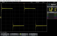
One image shows slew testing using an Agilent DSO-X-3024 digital storage scope with ARB generator. The scope has a built-in slew rate computation feature. The scope reports slew in MV/s (violet vertical spikes) which then must be converted to V/us by moving decimal places. A 1 kHz square wave was used and set to the LA-4's maximum output level of about 30Vp-p with about 5 dB compression at a 4:1 ratio. I did swing the frequency up to 20 kHz and the scope tracks slew with no notable change in the presentation.
The final result is roughly 10V/us. The Jensen input transformer is the limiting factor. When bypassed it results in about 20V/us. That said: (1) 10V/us satisfies Walt Jung's speed criterial; and (2) it's better than the stock slew rate of about 0.5V/us when the 4136 op amp stages are cascaded.
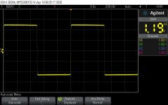
The other images show a 1 kHz square wave at normal line level with and without overshoot compensation components engaged on the secondary winding of the input transformer. This clearly shows why it's important to properly terminate a transformer if best dynamic performance is expected.
What's surprising is a dearth of information concerning transformers and their effect on system slew rate. It seems like each author that touches upon it is quick to exit, stage left.
Paul
Attachments

Update: I confirmed that the cadmium sulfide cell is contributing to THD. I lifted one end of the cell and THD drops to 0.002% at 1 kHz with +4 dBu at the input and output. The THD measurements are made with a Tektronix AA-501A analyzer and SG505 oscillator in a TM504 mainframe. That low level of distortion is attributed to the 990C discrete op amp and the AD797s.
With the cell engaged, THD is maximum at the cusp of cell illumination and is approximately 0.2% (30 kHz filter, no weighting). THD is minimum with higher levels of luminance to the cell -- which means THD drops with higher levels of gain reduction. Later, I'll validate with SpectraPlus software. The THD and memory characteristic completely follows the findings made in this video:
YouTube
I decided to replace the Jensen JT-11P-1 input transformer with a Jensen JT-6110K which allows for higher input voltage at low frequencies while the secondary output Z is better matched to the following AD797. The transformer is on order from Jensen.
More importantly, the new transformer has about 12 dB of voltage loss. This loss is needed because the original Urei design does not provide enough peak to average headroom. The original design (and with the JT-11P-1) measures +7.7 dBu after the active input transformer with a +4 dBu RMS input. All op amps in the chain clip at +22 dBu. Assuming a 15 dB peak-to-average ratio, that only leaves 1 dB of headroom. Worse, the LA-4 was also designed for use with older +8 dBu systems. In fact, the VU meter has a +8 dBu position. Anyone using +8 dBu = 0 VU at the input ran into headroom problems with voice, CD, or DAT material. Fortunately, by the time digital sources became popular, most broadcast and studio systems had changed to +4 dBu = 0 VU as a house standard. Still that means the stock LA-4 is on the ragged edge of clipping with most of today's audio sources.
The new level after the first AD797 will be -4.3 dBu with a +4 dBu level at the input terminals.
Next, I measured SNR with the 990C and AD797 op amps. With a 1 kHz sinewave referenced at +4 dBU at the input and output terminals, SNR is an impressive 91 dB as measured with the AA-501A (30 kHz filter, no weighting). This may not seem impressive by modern standards, but for a ca. 1970 design, it definitely is. The 990C and AD797 make this level of SNR performance possible.
I indicated earlier that I reverted to the RC4136 op amp in the control chain. I noticed about 1.5 dB of gain reduction drift as the unit warmed up. I replaced the 4136 with an OPA2991 which has excellent input offset voltage specs. The G/R meter now reads at 0 from time of powering and stays there.
Just a reminder to anyone taking measurements on these older designs: When the VU meter is selected to read either +4 or +8 output level, the meter's bridge rectifier is applied across the output transformer's secondary winding through a 3600 ohm ballistics build out resistor. That results in a small amount of distortion that completely disappears when the meter is set to the G/R position. Except for validating levels, the Urei's meter should normally be left in the G/R position.
More photos and measurements after the input transformer is changed...
Paul
> transformers and their effect on system slew rate.
Well-driven transformers do not slew. Passive devices generally can not slew-limit.
Amplifiers of poor current output driving high-C transformers can slew, of course.
The clipping just above nominal level may be *intentional*. Nevermind the DAT/CD of the future. These were mostly broadcast limiters. After the limiter was a transmitter which, if clipped, made real trouble (neighbor complaints, fed citations). Very many low-cost limiters would clip to hide their slow response.
And "polishing the sow's ear" comes to mind. The LA-2a was possibly a euphonic tool. I have never heard much love for the LA-4. My own design on similar parts was OK as a protection tool but never an "inspirational musical enhancement" (except that it avoided gross tape saturation in live recording).