I pulled a transformer out of a Kenwood KR-5340 and I want to use it in my own amplifier build, but the wire is kinda weird. I can't really find much info on transformers that are wired like this one. I think it has 1 primary and 2 secondary connections, but one of the secondarys pushes out more power than the primary.
I also want to buy an off the shelf power supply too, but I don't know what will work well with this transformer.
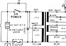
I measured the voltage on the output.
- red to red = 35v
-black to red = 17v
- orange to orange = 45v
- blue to blue = 7v
I have a pdf of the schematic that's hopefully attached.
Update: I did find some stuff on using a single power supply with an amp chip that needs Vee and Vcc. The issue was that I could not find a way to use this with a dual chip amp based on two mono chips, like the LM1875 or LM3886. I had to go and look for a new amp chip that could do stereo and I think I'm going to use the LM4766, it has .06 harmonic distortion and take power between 20v and 78v. I used these two videos to figure out some stuff, one for the single power supply YouTube, and one for learning about bridge rectifiers YouTube. Some issues I run into though is that John's video uses an off the shell power brick so I don't know what's happening between the transformer and his circuit. And the other video only seems to use the full wave rectifier as a Vcc and GND power supply. "The Current Source" is filtering the output of the rectifier which makes sense to me if all you want is Vcc, but I have no idea if I need to do that before using John's circuit. I feel like I only need the power to be filtered where it is being filtered in John's circuit since I don't think filtering the power before will help. I have no way to check any of this though since I do not want to buy parts till I know what I'm building since I will probably have to wait until next year until anything arrives. Plus I do not own an oscilloscope, I know you can use a computer sound card as one but I'm pretty sure it can't handle more than 10-30v dc.
If there is any more info on this single power supply circuit that JohnAudioTech made please tell me, because he is pretty much the only reference I have found to this.
I drew a little sketch on paper to show what I'm thinking: Imgur: The magic of the Internet
I also want to buy an off the shelf power supply too, but I don't know what will work well with this transformer.
I measured the voltage on the output.
- red to red = 35v
-black to red = 17v
- orange to orange = 45v
- blue to blue = 7v
I have a pdf of the schematic that's hopefully attached.
Update: I did find some stuff on using a single power supply with an amp chip that needs Vee and Vcc. The issue was that I could not find a way to use this with a dual chip amp based on two mono chips, like the LM1875 or LM3886. I had to go and look for a new amp chip that could do stereo and I think I'm going to use the LM4766, it has .06 harmonic distortion and take power between 20v and 78v. I used these two videos to figure out some stuff, one for the single power supply YouTube, and one for learning about bridge rectifiers YouTube. Some issues I run into though is that John's video uses an off the shell power brick so I don't know what's happening between the transformer and his circuit. And the other video only seems to use the full wave rectifier as a Vcc and GND power supply. "The Current Source" is filtering the output of the rectifier which makes sense to me if all you want is Vcc, but I have no idea if I need to do that before using John's circuit. I feel like I only need the power to be filtered where it is being filtered in John's circuit since I don't think filtering the power before will help. I have no way to check any of this though since I do not want to buy parts till I know what I'm building since I will probably have to wait until next year until anything arrives. Plus I do not own an oscilloscope, I know you can use a computer sound card as one but I'm pretty sure it can't handle more than 10-30v dc.
If there is any more info on this single power supply circuit that JohnAudioTech made please tell me, because he is pretty much the only reference I have found to this.
I drew a little sketch on paper to show what I'm thinking: Imgur: The magic of the Internet
Attachments
Last edited:
It looks like a pretty common transformer type.
Two primaries so it can be wired for 110 or 220 volt supply
One center-tapped secondary (Reds with Black CT)
Two other secondary windings.
What exactly did you want to know about it?
Do you have a project in mind for this transformer?
Two primaries so it can be wired for 110 or 220 volt supply
One center-tapped secondary (Reds with Black CT)
Two other secondary windings.
What exactly did you want to know about it?
Do you have a project in mind for this transformer?
Attachments
Hi
What is your supply voltage? 110 or 230?
For a 110v supply you should wire red/blue to the phase (+) and yellow/white to neutral (-).
If you have a 230v supply you should join white and blue together and protect them in a blank connector , connect red to Phase (+) and yellow to (-).
Your output voltages look to be correct.
I would put the fuse on the incoming phase (IMHO) not the neutral as shown on the schematic.
Hope this helps
I want to use it for a new amplifier. The Kenwood kept braking down and I didn't want to dig through every component to find a fix, plus I want to add a couple things.
I'm really confused on how to wire this since all power supply builds I find use something like this Antek AN-0125. I don't know if I can just ignore the red wire and just use the orange wires or if I can merge both the red and orange to get 80 volts. I'll probably use the blue wires for two arduinos if I can, because I want a relay bank for inputs. I don't want to just poke around since I never like to work with AC power, in this case though it's the better and hopefully cheaper option since I have a probably powerful transformer.
Are you sure it can take both 110 and 220? Is this the case for different wiring setups because on the back it says "AC 110-120v"
120v, I'm in the US. The timestamp tells me this is form is further east.
When I tested the voltage I joined red+blue and yellow+white, I just wired it with no specific polarity because the amp original came with a plug that didn't. I was worried so I did plug it into a surge protector and nothing went wrong.
When I tested the voltage I joined red+blue and yellow+white, I just wired it with no specific polarity because the amp original came with a plug that didn't. I was worried so I did plug it into a surge protector and nothing went wrong.
Dagwood is sure about his comments.
Apparently, you're not educated enough at this point to discern how and why this particular transformer operates.
In that case, respectfully speaking, you really need some education on electronics, and dangerous voltage components, before you hurt yourself.
Apparently, you're not educated enough at this point to discern how and why this particular transformer operates.
In that case, respectfully speaking, you really need some education on electronics, and dangerous voltage components, before you hurt yourself.
Yes your transformer can operate at both 120v and 230v. As mentioned before, its just how its wired.
As wiseoldtech suggested, please read through this as a minimum, it will give you the basics. Please be safe!!!
https://www.electronics-tutorials.ws/transformer/multiple-winding-transformers.html
Also it would be good if you could tell us the amp you are planning to build?? Plenty of knowledge here but we need some direction
Another thought, when working on a unknown transformer I always run them up on low volts through my Variac, if you just apply mains voltage to what you think is the primary but could be a secondary and you might just end up with over a 1000 volts on one of the pairs! Also good idea to use a lamp in series with the phase (Hot) feed
Amp Startup
Ok I looked at the basics a little and it looks like I wired the power input in parallel so I should hopefully be fine, unless more amperage is going into the transformer than needed.
I'm cool with the idea of using an 18 to 24v DC power brick instead of screwing around with AC power, I just don't know any high quality boards, schematics, or chips that can be used with DC power. I was thinking of using an lm1875 for this build since I saw JohnAudioTech's review of a lower budget mono amplifier board.
I need a two speaker amp, that can do 6-ohms for my dayton b652, with balance control, a headphone out, and maybe some bass and treble controls. If you could recommend a dc powered circuit that would be great.
Nothing wrong at all about asking, but it's a good idea to listen to the answers too!Why do you think I'm asking here before I start poking around?
You need to get some basic electronics knowledge before you can proceed with your project, in my opinion.
Look up (on the web) or get from a book information on power supplies and rectifiers, and the AC and DC situation may be more clear.
If you buy a 'amplifier board' from China that uses AC power, part of the board is a power supply that rectifies the AC to DC.
Having a good look at the Kenwood schematic would be instructive.
- Home
- Design & Build
- Construction Tips
- I need some help with a transformer.